Measure Camera Shutter Speed

julianE

Senior Member
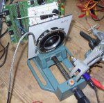
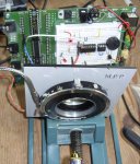
I still use film cameras, some of them very old ones, i would like to use the PICAXE to verify the shutter speed. Years ago i made a circuit that measured the shutter speed by using a phototransistor that charged a capacitor and then measured the voltage the capacitor reached, it was done with an op amp and it worked, but i think it would be better done with the picaxe. The way i did it before was by having a flashlight on the lens side and the sensor where film would be.

For the circuit I used a photo transistor with a 100K resistor going to the collector and the emitter grounded. Attached pin 6 of the 20X2 to the junction between collector and 100k resistor. Here is the code I used, I realize 20X2 is overkill but i've been playing with it so i used it,

main:
pulsin c.4,0,W1
if W1<>0 then
sertxd(#W1,13,10)
end if
goto main

I tried it with a Canon AE1P SLR and was getting values that were repeatable so it does seem to work. Example values for 1/60 are:
3938
3812
3852

Any improvement ideas? I also worry that this may not work with cameras that use a leaf shutter.

thanks in advance.
 

premelec

Senior Member
Oscilloscope?

I used to do this with an oscilloscope and high speed photocell - there's the rub - what's the response of the photo detector? If it's very fast compared to your shutter speed then no problems and you've got it... To deal with different shutter types some sort of diffuser is in order so the signal comes to the detector from the whole shutter action and not just one part. That's more of an optical problem than electrical... If you have a 'scope I'd give it a look to see if the signal is a good rectangular on/off or has dips in it... good luck!
 
Last edited:

julianE

Senior Member
some sort of diffuser would help with different type of shutters. thanks for the suggestion.

the simple method i'm using is not 100% effective sometimes i don't get a reading at all, maybe i should use some sort of an interrupt to start the timing. i went with photo transistor thinking that a photocell would not be fast enough to respond to a shutter. the fastest speed i'd be testing for is 1/1000 of a second. If i were to use a photocell i'd have to have some sort of an external circuit to generate a single pulse. i don't think using analog to digital would be fast enough.
 

Dippy

Moderator
In principle it looks fine.

I did a similar thing with LED --> photodiode+gubbins --> calibrated TEK scope.

A couple of comments and thoughts...

1. I totally agree with premelec re ensuring your sensor is much, much faster than your fastest shutter speed.
Personally I would have a much lower resistor value. If you had a 'scope you would probably see that the on-off slopes are much sharper/steeper with lower res values - as the lower values dissipate any charges much faster.
Check with Photo-Tr Data Sheet.

2. Not sure about this diffuser idea. An SLR shutter tends to be a vertical or horizontal blind shutter - it almost 'scans' across the negative. So picking up light over an area with a diffuser would, in my mind's eye, give an excessivley long result (depending on the light source; which could range from a bulb to a laser).
You want point-to-point I would have thought - as you are trying to replicate the light falling on a discrete point on the film.
I honestly can't see the problem with any type of shutter if you are just looking at a point.
You'll have to explain that one to me as I have done shutter testing on ancient bellows cameras too (leaf shutter) without any problems.
The physical position ('geometry') of the sensor may be important but I'll leave that to your imagination.

3. Calibration. Without a calibrated scope or other device you have nothing to compare it with/against. This means your numbers are relative. I would suggest using a crystal unless you have something fancy. You can be pretty confident that a crystal is bang on. I have never had a crystal which has been measurably 'out'.
For extra confidence buy several crystals and try them.
Crystals are better than resonators are better than internal resonator.
A faster crystal will give better resolution, though you will have to take care at slower shutter speeds icw pulsin timeouts - hey, you even have 2 switchable/swappable crystals at different Fs.

Anyway, those are my early Sunday morning thoughts :)

I'm sure eclectic can find some old links on this subject....
 

Dippy

Moderator
Haha.
You have the patience of a saint ec.
(Though I must admit it saves a lot of repetitive typing :) )

Someone should write a book.
 

julianE

Senior Member
Thank you for all the help. The only link i missed out is the one on Laser sticky, i read the others before i posted. To be honest i wanted to make this quick and dirty but i see now that i need to make it tighter. I initially planned on using an infrared detector/receiver pair but was dismayed buy the narrow beam angle needed, now i see i really need the narrow beam for it to work with the leaf shutters of which i have many. Sounds like a few of us out there with film cameras. As far as accuracy, with film there is enough latitude so as not to be that important, if i'm with in a 1/2 a F stop it will be fine.

as far as calibration i think all i'm going to use is one of my modern electronic controlled SLRs and I do have a mamiya with an electronic leaf shutter, just in case there are diferences between leaf and curtain shutters.

I tried lower value resistors and it was not as crisp as a 100k i think i'll try something lower, like 47K.

As far as the O'scope, i have one but it's such a hassle to get the monster out and set up. Computers have made me lazy...lazier :)

i guess, i'll have to make some sort of a bench. Put the camera on bulb setting, shine a beam 'till it strikes the photo transistor and then proceed to test at different shutter speeds.

Again, thank you or all the help, this forum is amazing, top notch folk.
 

Dippy

Moderator
It will be worth getting your monster out ;)

Without a 'tight' setup you have a lot of variables; ph-tr speed and response , reflections and lens refractions causing multipath to your receiver - and probably many other little things.

I used a couple of 3mm spaced washers in front of my ph/diode so that most off-angle illumination was ignored. After all, you are trying to emulate a tiny discrete area of film which is why I didn't think a diffuser was the best idea.

If you dig out your monster you will be able to see pulse shape changes as you change your setup.

You should have it up and running in an hour :)
And for the sake of a few pennies a crystal will give you extra confidence.
Good luck.
Make it good and then let us know how you did it in detail. Then people can link to this thread to get ideas for their own design versions.
 

fernando_g

Senior Member
What phototransistor p/n are you using.
Some devices have a very wide base, for higher sensitivity...but there is never a free lunch in electronics, and the tradeoff is speed.

Usually the phototransistor takes much longer to turn off than turn on...some phototransistors with base lead will allow you to experiment with different resistance values to optimize your speed/sensitivity tradeoffs.

For that, as Dippy has mentioned, you REALLY need the scope.
 

fernando_g

Senior Member
Here is an example using a MRD360 phototransistor.
The blue trace is the voltage driving an IR diode, and the yellow trace is the phototransistor's response employing the manufacturer's test circuit.

I used an IR LED because I know those are fast for sure, used to transmit data, so any difference between the driving voltage and received voltage must be related to the phototransistor response.
 

Attachments

julianE

Senior Member
Fernando,

I'm using the radio shack IR pair,

http://www.radioshack.com/product/index.jsp?productId=2049723&tab=summary

i really need to build some sort of a test jig since i need it to be precise, very directional. so far i've only tested with a very bright flashlight on the lens side.

i need to look at O'scopes that use a pc for interface. i do have a very good old school scope but i'll need to dig it out, have not used it in a dozen years.

i'm also tempted to go to an older method i used, have a circuit that charges a capacitor and use the ADC to measure the voltage the cap reached, the longer the shutter is open the greater the voltage on the cap.
 

eclectic

Moderator
@julianE

Following on from some of the points in this thread,
I've been testing an old Synchro Compur.
(1 s to 1/400s)

Light source is a cheap Laser pointer,
flashing at 10kHz, under pwmout.

Receiver = BPW34 photodiode , 4k7 to ground.

TX program
Code:
#picaxe  28X1
setfreq em4  ; 4MHz resonator
pwmout 1 , 99, 200 ;10000 @ m4

do
loop
Rx/counter
Code:
;http://www.picaxeforum.co.uk/showthread.php?t=13447


#picaxe 20X2
#terminal 9600
setfreq m8
main:
if pinc.1 = 1 then

count c.0 , 4000, W1
sertxd (#w1,cr,lf)
endif
goto main

#rem

counts pulses from a 10kHz pwm laser
Switch allow time to press cable release.
1. The conditions are NOT calibrated, but the results are consistent.

2. Because of the mechanical construction, (and age?), there is a significant
difference between “centre” and “edge” readings, especially at the “high-speed” end.
For example, 1/400s centre = 44. Edge = 26.

e
 

Attachments

julianE

Senior Member
eclectic,

does it make sense to have such a large difference between edge and center, have you taken photos at 1/400, seems to me it would have a vigneting like effect.
 

eclectic

Moderator
eclectic,

does it make sense to have such a large difference between edge and center, have you taken photos at 1/400, seems to me it would have a vigneting like effect.
I still haven't got round to rebuilding my darkroom,
so I can't answer the vignetting question.
The shutter was tested on its own, without lens.

I can only suggest that that you try the Pwm-Laser method,
or use an LED in a tube, and then compare results.

e
 
Last edited:

Dippy

Moderator
I could only find some tatty diagrams of that type of shutter, so I couldn't follow it too well.

Is it a multi-leaf type that opens from the middle outwards and then back again?
If that is the case then I'm not surprised at a difference centre-edge, though I am surpised at the amount of difference. It's 'asking' for vignetting effects with that variance.

Have you scoped it to see if you are getting any wierd things or reflections or nasty pulse shapes? And checked any differences between centre and edge.

Some 'scope images would be nice to see if you'd biased the photo-diode well.

Personally, I would shield the Phot-diode so that only light from directly ahead was detected.

Nevertheless, with calibration, a nice setup.
 

eclectic

Moderator
@Dippy / julianE.

Off Picaxe topic, but very relevant to the last couple of posts.

I've copied a section from
The Manual of Photography
(Jacobsen ….)
(7th and 8th Editions have the same text.)

Basically, see the last two sentences of the quote.

The text was followed by lots of optic diagrams and equations,
which made my head ache. :)

My shutter was “naked”; I'd removed the front and rear lens groups.
I estimate that the diaphragm-shutter gap is < 1mm

e
 

Attachments

Dippy

Moderator
Yes, that confirms the grotty drawings I saw.
So, if it's operation isn't fast enough compared to the exposure time then there can be problems. Which I guess might happen if old and dirty?

Anyway, you've proved the principle.
 

eclectic

Moderator
Oh!
Have I got the wrong end of the proverbial?

From my cursory reading, and fading memory,
I'd assumed that the shutter blades would act
in a similar way to an Iris diaphragm.

Any "sticky" problems would relate to overall exposure,
rather than vignetting.

e
 

Dippy

Moderator
Well, I've probably got the wrong end... I only saw a tatty 10th generation image of the shutter.
(And i really don't want to start 50 posts on shutter design :) )


I've probably got it all wrong, but hey, what the heck ;)
 
Top