MAP sensors

Jaguarjoe

Senior Member
I would like to build a simple vacuum gauge with a bi-color LED output. Low=red, medium=red+green, and high vacuum = green. This will help teach my wife to learn how to live with $4/gal fuel.
Anyhow, I need to know if an 08M can work with 160Hz square waves. I can get MAP (Manifold Absolute Pressure) sensors from the wrecking yard for next to nothing. Some provide a semi low impedance output of 0.1 to 4.9 VDC which programatically would be very easy to use but would require a buffer amplifier between the sensor and the 08M. Or, I can also get digital sensors which put out 5v square waves from 80Hz to 160Hz. These are desirable because I would not need any extra parts. But, can the 08M handle that high of a frequency?
 

BeanieBots

Moderator
160 Hz has a period of over 6mS so the 08M should be able to do something useful within that time even without the need for over-clocking.

However, why would the "semi low impedance output of 0.1 to 4.9 VDC " need any buffering? Sounds ideal for the 08M to monitor direct.
 

lbenson

Senior Member
As for the real magic in this application--how will it teach +anyone+ to live with $4 gasoline?
 

inglewoodpete

Senior Member
The 08M does not need to monitor every cycle of the square wave. I would suggest using the PulsIn command to determine the length of pulses. With a bit of mathematics applied, you could determine which colour to flash. You will probably need to introduce some hysterysis to stop the colours jumping about too much.

How clean is the square wave? You don't want nasty over- and under-voltage spike killing you PICAXE.

Don't tell your wife what it means: when she sees the red flashing light, she'll probably drive home at 5 mph;)
 
Last edited:

Dippy

Moderator
Either sensor should be easy to interface.

The analogue signal is just as BB says ; ideal. Though a little RC filtering would be good.

The digital signal is as IPete says; easy. Just a little maths. Inlcude a little i/p protection to maintain happiness.

If these things don't make any sense then please ask before diving in head-first.

And then we get onto powering PICAXEs from the vehicle supply.
do a search on automotive or vehicle power supplies.
It isn't difficult or magic. It just requires thought and care and sensible component choice.... and heeding advice.
Electronics is easy to POP if you are careless, but with a little heave-ho you can make it really tough.
I DO hope we don't get 10 posts of panic and mission-critical ;)
 

BillyGreen1973

Senior Member
OT:
I would love fuel to be $4/Gal! :rolleyes:

Just put a little sticker on the rev counter at 2500 revs, and tell her if you go above this line for longer than 30 seconds you will damage the engine.
Works a treat, my wife says the car drives better now the sticker is there ;)
 

mega

New Member
$4 per US gallon, around $1.08 a litre, or around AU$1 per litre, not expensive at all....

Enough of that though....

It's at this stage that I can post up what I've done with four Ford M.A.P. sensors, I use it to balance my motorcycle carburettors, works a treat.

I use count, I originally used an 18X but then changed to an 18M2, I would see no problem with using an 08M to drive a few leds, you just need to set your limits for what led you want to light up.

I can post up the code for 18X and 18M2 if you like, I have no issues with it being used by anyone, and you can hack it as much as you like, though I think you would like to have a go for yourself, here is a picture of the display I have, complete with thongs (Jandals to you Kiwis and flip-flops to others, not forgetting my beer-belly too.....)


Adamey

Senior Member
^ I did a very similar thing to balance automotive carbs. Instead of using MAP sensors I used MAF sensors and plotted the results on a scope. Not only could I measure airflow through the carbs, but I could also see how they responded the throttle changes by watching the graphs.
 

Jaguarjoe

Senior Member
As for the real magic in this application--how will it teach +anyone+ to live with $4 gasoline?
Engine manifold vacuum is a simple indicator of engine load. High vacuum is closed throttle and light load, low, or no vacuum is heavy load at or near WOT. By setting this up right she should be able to see how her lead foot is costing us money.
 

fernando_g

Senior Member
JJ;
You are absolutely correct about manifold pressure beign a perfect tool to educate a driver on the basics of economy driving.

Case in point: accelerating in a grade. Even on a shallow grade it requires a substantial increase in power. But with all the crature comforts and isolation that new vehicles provide, one does not really notice what is going on.

Thus such a gauge wil be really valuable.
In fact, your post got me thinking about the possibilities... a color-coded bargraph display! A sound alert, that will become active if extreme low-vacuum is maintained for several seconds. An event counter of how many times a certain threshold are exceeded. The posibilities are endless.

One would require something more powerful than a lowly 08M though.
 

Jaguarjoe

Senior Member
I just want something simple- green-orange-red. Something that does not require taking your eyes off the road, something that can be caught in your peripheral vision.
 

mega

New Member
It's a fairly simple program, I use a 4 bit interface to the LCD but that's not what you want, all it does is read how many counts in a time period and display that count, it's all I need to balance the carbies, just get to the same numbers for each MAP sensor, what you will probably do is read how many counts you get and decide which led you want to light up.

With the ford MAP sensors, they are powered up with 5volts, the output is therefore a 5volt peak voltage frequency, there are 3 wires on the MAP sensor, 0v, 5v and output, you can use an earlier Ford sensor, the maximum frequency is 80Hz though.

This is the 18M2 code.... I think it may put on to the right track, have fun...

Code:
#rem

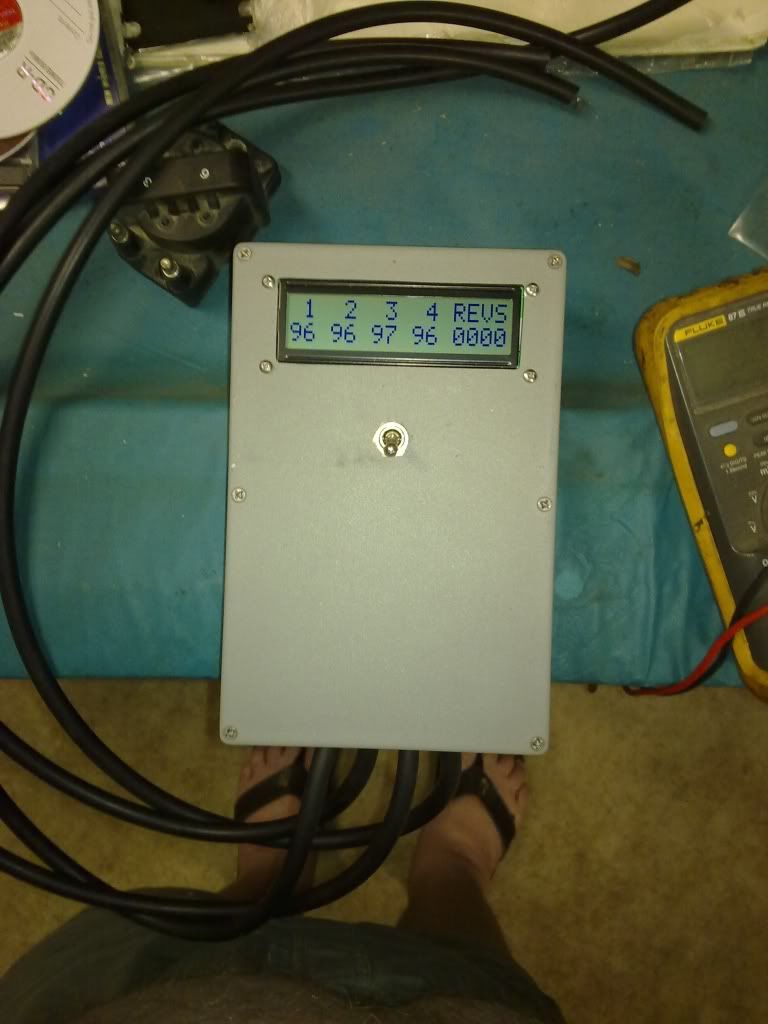
Four cylinder motorcycle carburettor balancing tool using 4 map sensors
By R. A. Hodge. 2011/01/04

Manifold Absolute Pressure Sensor data
(frequency output)
29.92 inHg= Sea Level
100 kPa = Sea Level

Manifold Vacuum                  MAP Frequency

inHg		PSI		kPa		Hz		My Display
								
0.00		0.00		0.0		159		95
3.00		1.47		10.16		150		90
5.00		2.46		16.93		146		88
6.00		2.95		20.32		141		85
8.00		3.93		27.09		134		80
9.00		4.42		30.48		133		80
11.00		5.40		37.25		126		76
12.00		5.89		40.64		125		75
13.00		6.39		44.02		121		73
14.00		6.88		47.41		119		71
15.00		7.37		50.80		117		70
16.00		7.86		54.18		114		68
17.00		8.35		57.57		111		67
18.00		8.84		60.95		109		65
19.00		9.33		64.34		107		64
20.00		9.82		67.73		104		62
21.00		10.31		71.11		102		61
23.00		11.30		77.89		97		58
24.00		11.79		81.27		95		57
27.00		13.26		91.43		88		53
30.00		14.73		101.59        80		48


4 bit mode LCD Example for Picaxe 28X2
Based on Hippy's code by Svejk,
modified for Picaxe 18M2 by me.

b.7 --> DB7
b.6 --> DB6
b.5 --> DB5
b.4 --> DB4
b.3 --> EN
b.2 --> RS

#endrem


#picaxe 18M2

setfreq m8

  dirsB = $FF
  
  SYMBOL  MAP1      = b20
  SYMBOL  MAP2      = b21
  SYMBOL  MAP3      = b22
  SYMBOL  MAP4      = b23
  
  symbol Counter = b27
  symbol chr     = b26

'LCD
  symbol RSCMDmask = %00000000 	'select Command register
  symbol RSDATmask = %00000100 	'select Data register
  symbol En    = b.3
  symbol rsbit = b25
  
  
'OnPowerUp:
  eeprom  0, ($33, $32, $28, $0C, $06, $01)


'Initialise LCD:
  pause 50
  for counter = 0 to 5
    read counter, Chr
    gosub SendCmdLCD 
    pause 30
  next counter
  
;Message:
  
  chr = $80                  'send cursor to begining of top line
  GOSUB SendCmdLCD
  for counter = 0 to 15
    lookup counter, ("Carbie  Balancer"), chr
    gosub SendDataLCD
  next counter


  chr = $C0                  'send cursor to begining of bottom line
  GOSUB SendCmdLCD
  for counter = 0 to 15
    lookup counter, ("by R. A. Hodge  "), chr
    gosub SendDataLCD
  next counter 
  
  pause 6000


'DisplayTopLine:

  chr = $80                  'send cursor to begining of top line
  GOSUB SendCmdLCD
  for counter = 0 to 15
    lookup counter, ("CARB 1  2  3  4 "), chr
    gosub SendDataLCD
  next counter
  
  
'DisplayEndBotLine:

  chr = $C0                  'send cursor to display 'READ' on bottom line
  GOSUB SendCmdLCD
  for counter = 0 to 15
    lookup counter, ("READ            "), chr
    gosub SendDataLCD
  next counter
  
  
do   'main program

 count C.0, 1200, MAP1   ' count pulses in 0.6 seconds each sample
 count C.1, 1200, MAP2   ' or 2.4 seconds total sample time
 count C.2, 1200, MAP3
 count C.6, 1200, MAP4
       
       
bintoascii MAP1,b0,b1,b2	 'convert No.1 sensor data to ascii
    
        chr = $C5                  'send cursor to under the number '1'
        GOSUB SendCmdLCD
    
         FOR counter = 0 TO 1            'display counts on lcd
          lookup counter, (b1,b2), chr
          gosub SendDataLCD
         next counter
         
         
 bintoascii MAP2,b0,b1,b2	 'convert No.2 sensor data to ascii
    
        chr = $C8                  'send cursor to under the number '2'
        GOSUB SendCmdLCD
    
         FOR counter = 0 TO 1            'display counts on lcd
          lookup counter, (b1,b2), chr
          gosub SendDataLCD
         next counter
         
         
 bintoascii MAP3,b0,b1,b2	 'convert No.3 sensor data to ascii
    
        chr = $CB                  'send cursor to under the number '3'
        GOSUB SendCmdLCD
    
         FOR counter = 0 TO 1            'display counts on lcd
          lookup counter, (b1,b2), chr
          gosub SendDataLCD
         next counter
         
         
 bintoascii MAP4,b0,b1,b2	 'convert No.4 sensor data to ascii
    
        chr = $CE                  'send cursor to under the number '4'
        GOSUB SendCmdLCD
    
         FOR counter = 0 TO 1            'display counts on lcd
          lookup counter, (b1,b2), chr
          gosub SendDataLCD
         next counter    

 loop  
 
'LCD Routines
SendCmdLCD:
  RSbit = RSCMDmask

SendDataLCD:
  pinsB = chr & %11110000 | rsbit
  pulsout En, 2

  pinsB = chr * %00010000 | rsbit
  pulsout En, 2

  rsbit = RSDATmask
 return
 

papaof2

Senior Member
This has been a useful thread for me. My wife isn't 'mechanically inclined', so doesn't notice when the car's engine is straining to maintain speed on a hill (4 speed automatic with very poorly designed 'economy' in the engine/transmission control units - designed to wait a LONG time before downshifting). This means the vehicle will run to 100% load at highway speed (2200 rpm or so), then downshift to second gear - obviously sending the engine to somewhere around 5000 rpm. When I'm driving, I 'hear' the change in engine load and manually downshift to third. The engine is in a better point on the torque curve (peaks at 3800 rpm) and maintains speed with no problem.

Using the ideas here, I could design a solenoid-based 'kicker' that does the downshift/upshift as needed based on engine load (the 3-4 shift is less than an inch of horizontal travel). This would be the equivalent of me being in the passenger seat and awake. The 'kicker' would get a momentary pulse to do the downshift or upshift based on eqgine vacuum. There would be some delay after a downshift to ensure the engine load has dropped sufficiently for a long enough period to justify an upshift. As we make several 600 mile trips each year, there would be plenty of opportunity for field testing ;-)

Yes, I am aware of the safety issues with any modification to a vehicle (been doing work like brakes and tie rods for ~50 years) and the power issues associated with using a microprocessor in a vehicle. I once built devices using TTL chips in a telephone switching office - lots of transients from relays running on 48 volts DC. The Bell Labs guys said it couldn't be done, but they were working from datasheets and I was working in the real world where I found ways to ensure the chips ignored the noise.

Maybe there should be an event memory and a display of some type?

John
 

fernando_g

Senior Member
JJ:
You can still do it.
The motivation of us tinkerers, is the learning process and the satisfaction of doing something useful.

And this "Econodriver" unit, provides way too much information for those that are not technically inclined. A green/yellow/red LED will be sufficient information for our respective spouses or children.

What I like about this unit is that it can be connected to an OBD-II port, making it transportable between vehicles.
 
Top