Louder Piezo

giuseppe

Member
Hello all,

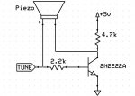
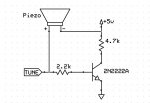
So I have been using a small piezo buzzer I found a long time ago from a basic stamp II kit (http://www.parallax.com/StoreSearchResults/tabid/768/List/0/SortField/4/ProductID/106/Default.aspx?txtSearch=piezo+speaker). It works fine and the tune command works well with it. However, I would like to be a bit louder. Anyone know where I can buy a louder one from? Or am I going to have use an OPAMP and amplify the signal from the PICAXE to the piezo? A non-inverting OPAMP? http://www.electronics-tutorials.ws/opamp/opamp_3.html
 

inglewoodpete

Senior Member
If you are "manually" producing tones, you can toggle 2 output pins in opposite phase to get about (4v * 2) P-P (~trippling the sound level) across the piezo - no extra hardware required.

If you want to use the tune/note commands etc, you could use an NPN transistor (2.2k ohm resistor PICAXE O/P to Base; 0v to Emitter; 4.7k ohm resistor from +5v to Collector). Connect the piezo between the collector and the PICAXE output. This will also give about 8v P-P across the Piezo, also ~trippling the sound level.
 

Richbk

New Member
If you are "manually" producing tones, you can toggle 2 output pins in opposite phase to get about (4v * 2) P-P (~trippling the sound level) across the piezo - no extra hardware required.
This is an interesting idea, would it work with a 3v battery? I'm struggling to get my head around it... essentially you can have a max of 3v on one pin and 0v on another? Unless the picaxe can invert and offer -3v some how?
I'm using the sound command by the way.

Thanks
 

hippy

Ex-Staff (retired)
This is an interesting idea, would it work with a 3v battery? I'm struggling to get my head around it... essentially you can have a max of 3v on one pin and 0v on another?
The way it works is the piezo is between two pins, 3V/0V then both are inverted to 0V/3V. With 3V/0V the current flows from first to second pin, the piezo element moves forward, when 0V/3V the current is reversed, flows from second to first, the piezo moves backwards.

You get twice as much movement ( forward plus backwards ) than you would with 3V/0V and the 0V/0V a one pin connection gives ( which only gives forward or backwards movement ).
 

Richbk

New Member
Ah that makes sense, thanks a lot hippy.

Can I assume that the sound command won't work in this instance? I've found your previous post about using HPWM, is this the best/only way?

Thanks again for your help
 

hippy

Ex-Staff (retired)
Ah that makes sense, thanks a lot hippy.
I think it's Westaust55 that deserves credit for once describing it in those terms ( apologies if it was some else who should get the credit ).

Can I assume that the sound command won't work in this instance? I've found your previous post about using HPWM, is this the best/only way?
HPWM can automatically generate the two complementary signals which is why that's useful, most other output commands don't, use just one pin, TUNE and SOUND included, so you do need a means to generate a second signal which is the inverse of the first.

If you've got the right PICAXE you can use some of the on-chip hardware to act as an inverter to save having to add an external inverter, but you have to use POKESFR/PEEKSFR to set it up. Both analogue comparators ( for X2 ) and the DSM hardware ( for M2 ) can be used to do that.
 

Richbk

New Member
I'm using an 08M2 so the HPWM isn't an option for me. Using the picaxe as an inverter sounds interesting, do you know if the 08M2 is capable of this?
 

hippy

Ex-Staff (retired)
Using the picaxe as an inverter sounds interesting, do you know if the 08M2 is capable of this?
It should work on an 08M2 for PWM or any output command.

I'll see if I can get it working and I'll post the code. Not sure if it can be done with just two output pins or if it needs an additional input pin as well.
 

Richbk

New Member
It should work on an 08M2 for PWM or any output command.

I'll see if I can get it working and I'll post the code. Not sure if it can be done with just two output pins or if it needs an additional input pin as well.
Thank you very much, that's very kind of you.
 

hippy

Ex-Staff (retired)
Some example programs for the 08M2, showing Output 0 being the inverse of some other output. Needing to be Output 0 is a limitation of the silicon. The input to the inverter can be any of three pins and we can use the output pin we are controlling also as an input to the DSM - Not a recommended configuration but seems to work.

In the first example, connect LED's to Output 1 and Output 0 to see that the two outputs are the opposite of each other ...
Code:
#Picaxe 08M2
#No_Data

;  .----_----.         2 x LED
; -|+V     0V|-    ___
; -|SI  SO/O0|----|___|--|>|--.
; -|X4     X1|----|___|--|>|--{
; -|I3     X2|-              _|_ 0V
;  `---------'


PokeSfr $FC, %11000000 ' SFR $39C MDCON
PokeSfr $FD, %00000001 ' SFR $39D MODSRC
PokeSfr $FE, %01000000 ' SFR $39E MDCARL
PokeSfr $FF, %00000000 ' SFR $39F MDCARH

Do
  High 1 : Pause 500
  Low  1 : Pause 1000
Loop
In the second, same configuration except we put a piezo across Output 0 and Output 1. Use Output 0 or Output 1 and the other lead of the piezo to 0V to compare with normal volume ...
Code:
#Picaxe 08M2
#No_Data

;  .----_----.      |   
; -|+V     0V|-   .-|
; -|SI  SO/O0|----| |   Piezo
; -|X4     X1|----| |  Sounder
; -|I3     X2|-   `-|
;  `---------'      |


PokeSfr $FC, %11000000 ' SFR $39C MDCON
PokeSfr $FD, %00000001 ' SFR $39D MODSRC
PokeSfr $FE, %01000000 ' SFR $39E MDCARL
PokeSfr $FF, %00000000 ' SFR $39F MDCARH

Do
  Pause 1000
  Sound 1,( 100,10, 110,10, 115,20 )
Loop
Note that, because Pin 1 defaults to an input on reset / program download, you don't get the cacophony of noise a piezo between Output 0 and 0V will normally give during download.

And finally, how to create the 'HPWM' effect using PWM and the inversion. Note it's Output 0 and Output 2 in this one ...
Code:
#Picaxe 08M2
#No_Data

;  .----_----.         |   
; -|+V     0V|-      .-|
; -|SI  SO/O0|-------| |   Piezo
; -|X4     X1|-  .---| |  Sounder
; -|I3     X2|---'   `-|
;  `---------'         |


PokeSfr $FC, %11000000 ' SFR $39C MDCON
PokeSfr $FD, %00000011 ' SFR $39D MODSRC
PokeSfr $FE, %01000000 ' SFR $39E MDCARL
PokeSfr $FF, %00000000 ' SFR $39F MDCARH

Do
  Pause 1000 : PwmOut 2, 199, 400
  Pause 1000 : PwmOut 2, OFF
Loop
 

Richbk

New Member
You sir are THE man! I really can't thank you enough! I went with the second option so I can use the sound command and as you said the volume is doubled!

Thanks again for all your help :)
 

giuseppe

Member
If you are "manually" producing tones, you can toggle 2 output pins in opposite phase to get about (4v * 2) P-P (~trippling the sound level) across the piezo - no extra hardware required.

If you want to use the tune/note commands etc, you could use an NPN transistor (2.2k ohm resistor PICAXE O/P to Base; 0v to Emitter; 4.7k ohm resistor from +5v to Collector). Connect the piezo between the collector and the PICAXE output. This will also give about 8v P-P across the Piezo, also ~trippling the sound level.
Sweet, I am going to give it try.
 

giuseppe

Member
Can I give it a shot on how it works?

I am guessing that when a high is at the picaxe pin, the transistor is saturated acts like a switch to ground, which makes the piezo connect to ground (exception of the voltage drop across the collector and emitter but close to ground enough) When the pin goes low, the current is now reversed in the piezo since the transistor is off and the other end of the piezo is now getting the 5V signal. Am I right?

I guess it is the same as toggling the picaxe pins in a previous post. Very clever!
 

giuseppe

Member
Actually, now that I am thinking about it, unless after the tune command I make the pin an input, wouldn't the piezo be held in one position? If so, does this cause any kind of damage?
 

Richbk

New Member
Actually, now that I am thinking about it, unless after the tune command I make the pin an input, wouldn't the piezo be held in one position? If so, does this cause any kind of damage?
It does appear to do this, the only thing I can think of is to turn off the inverting picaxe code.

Code:
#Picaxe 08M2
#No_Data

;  .----_----.      |   
; -|+V     0V|-   .-|
; -|SI  SO/O0|----| |   Piezo
; -|X4     X1|----| |  Sounder
; -|I3     X2|-   `-|
;  `---------'      |


PokeSfr $FC, %11000000 ' SFR $39C MDCON
PokeSfr $FD, %00000001 ' SFR $39D MODSRC
PokeSfr $FE, %01000000 ' SFR $39E MDCARL
PokeSfr $FF, %00000000 ' SFR $39F MDCARH

Do
  Pause 1000
  Sound 1,( 100,10, 110,10, 115,20 )
Loop
Normally I'd suggest setting all of the values to 00000000 like so:


PokeSfr $FC, %00000000 ' SFR $39C MDCON
PokeSfr $FD, %00000000 ' SFR $39D MODSRC (should this be MDSRC?)
PokeSfr $FE, %00000000 ' SFR $39E MDCARL
PokeSfr $FF, %00000000 ' SFR $39F MDCARH

BUT according to page 31: http://ww1.microchip.com/downloads/en/DeviceDoc/41441B.pdf
The "value on all other resets" is:
MDCON 0010 ---0
MDSRC u--- uuuu
MDCARL uuu- uuuu
MDCARH uuu- uuuu

I'd assume then that you'd have to set the following:

PokeSfr $FC, %00100000 ' SFR $39C MDCON
PokeSfr $FD, %00000000 ' SFR $39D MODSRC (should this be MDSRC?)
PokeSfr $FE, %00000000 ' SFR $39E MDCARL
PokeSfr $FF, %00000000 ' SFR $39F MDCARH

Hippy does that sound right or have I got it completely wrong? Is it even something that can be turned on/off like this before/after the sound? Or is it just easier/better to set it as an input as suggested by giuseppe?

Thanks in advance for any help
 

techElder

Well-known member
You're not going to damage the piezo by keeping a voltage on it. It's designed to have a voltage on it.
 

inglewoodpete

Senior Member
Yep. It behaves like a capacitor. The piezo material flexes as the voltage across it changes. If the voltage changes fast enough, the piezo makes sound.
 

hippy

Ex-Staff (retired)
You're not going to damage the piezo by keeping a voltage on it. It's designed to have a voltage on it.
I recall reading somewhere that it's best not to keep current permanently flowing through a piezo but I don't have a citation nor know how true that is.

I might do a bit of Googling later, but making the pin an input would seem to be no bad thing. The only issue in allowing a Piezo inverting driver to float is the risk of simply creating a free-running oscillator so that might require thinking about.

I'd assume then that you'd have to set the following:

PokeSfr $FC, %00100000 ' SFR $39C MDCON
PokeSfr $FD, %00000000 ' SFR $39D MODSRC (should this be MDSRC?)
PokeSfr $FE, %00000000 ' SFR $39E MDCARL
PokeSfr $FF, %00000000 ' SFR $39F MDCARH

Hippy does that sound right or have I got it completely wrong? Is it even something that can be turned on/off like this before/after the sound? Or is it just easier/better to set it as an input as suggested by giuseppe?
Clearing MDCON will disable the DSM hardware, return Output 0 to a normal Output 0 / Serial Out pin, and then set Output 1 to an input. Probably ideally, poke $00 to $FC, $FD, $FE, $FF.

MODSRC / MDSRC - It seems to be the later in the latest datasheets. Microchip are sometimes inconsistent in naming SFR registers and bits so it may have been a case of that, my pulling the name from a header file with a typo in it or adding one myself!
 

giuseppe

Member
I recall reading somewhere that it's best not to keep current permanently flowing through a piezo but I don't have a citation nor know how true that is.
Hmm okay. The reason I asked was because yesterday at work (I am the intern) the one engineer was telling me that for one of their closed loop optic systems, they needed to bias the piezo after it has been used because it has some hysteresis. Maybe damage was the wrong word to use, maybe it would alter the way it operates after keep a voltage on it.
 

techElder

Well-known member
That's really funny! I didn't get the impression you were building something to go into the International Space Station! :D

A piezo element has such a high impedance that there is very little current flow at DC (if you could measure it at all.)

Hmm okay. The reason I asked was because yesterday at work (I am the intern) the one engineer was telling me that for one of their closed loop optic systems, they needed to bias the piezo after it has been used because it has some hysteresis. Maybe damage was the wrong word to use, maybe it would alter the way it operates after keep a voltage on it.
 

giuseppe

Member
That's really funny! I didn't get the impression you were building something to go into the International Space Station! :D

A piezo element has such a high impedance that there is very little current flow at DC (if you could measure it at all.)

Ha I don't think I would use a PICAXE for any space station applications! Though, it would be cool to do so!
 

Richbk

New Member
Some example programs for the 08M2, showing Output 0 being the inverse of some other output. Needing to be Output 0 is a limitation of the silicon. The input to the inverter can be any of three pins and we can use the output pin we are controlling also as an input to the DSM - Not a recommended configuration but seems to work.

In the first example, connect LED's to Output 1 and Output 0 to see that the two outputs are the opposite of each other ...
Code:
#Picaxe 08M2
#No_Data

;  .----_----.         2 x LED
; -|+V     0V|-    ___
; -|SI  SO/O0|----|___|--|>|--.
; -|X4     X1|----|___|--|>|--{
; -|I3     X2|-              _|_ 0V
;  `---------'


PokeSfr $FC, %11000000 ' SFR $39C MDCON
PokeSfr $FD, %00000001 ' SFR $39D MODSRC
PokeSfr $FE, %01000000 ' SFR $39E MDCARL
PokeSfr $FF, %00000000 ' SFR $39F MDCARH

Do
  High 1 : Pause 500
  Low  1 : Pause 1000
Loop
In the second, same configuration except we put a piezo across Output 0 and Output 1. Use Output 0 or Output 1 and the other lead of the piezo to 0V to compare with normal volume ...
Code:
#Picaxe 08M2
#No_Data

;  .----_----.      |   
; -|+V     0V|-   .-|
; -|SI  SO/O0|----| |   Piezo
; -|X4     X1|----| |  Sounder
; -|I3     X2|-   `-|
;  `---------'      |


PokeSfr $FC, %11000000 ' SFR $39C MDCON
PokeSfr $FD, %00000001 ' SFR $39D MODSRC
PokeSfr $FE, %01000000 ' SFR $39E MDCARL
PokeSfr $FF, %00000000 ' SFR $39F MDCARH

Do
  Pause 1000
  Sound 1,( 100,10, 110,10, 115,20 )
Loop
Note that, because Pin 1 defaults to an input on reset / program download, you don't get the cacophony of noise a piezo between Output 0 and 0V will normally give during download.

And finally, how to create the 'HPWM' effect using PWM and the inversion. Note it's Output 0 and Output 2 in this one ...
Code:
#Picaxe 08M2
#No_Data

;  .----_----.         |   
; -|+V     0V|-      .-|
; -|SI  SO/O0|-------| |   Piezo
; -|X4     X1|-  .---| |  Sounder
; -|I3     X2|---'   `-|
;  `---------'         |


PokeSfr $FC, %11000000 ' SFR $39C MDCON
PokeSfr $FD, %00000011 ' SFR $39D MODSRC
PokeSfr $FE, %01000000 ' SFR $39E MDCARL
PokeSfr $FF, %00000000 ' SFR $39F MDCARH

Do
  Pause 1000 : PwmOut 2, 199, 400
  Pause 1000 : PwmOut 2, OFF
Loop
Sorry to resurrect an old thread but I'm having trouble moving this over from an 08m2 to a 14m2. I've gone for the basic LED setup to test it but whilst output 1 (b.1) is flashing, it's not being mirrored on any of the other pins (namely output 0 (b.0)). Is the setup different for a 14m2? I feel like I'm missing something obvious.
 

radiogareth

Senior Member
If you want to make a LOT of noise re-purpose a piezo siren window alarm. They have a transistor driving a step up transformer that drives the piezo. Remove the usually logic chip based drive signal to the base of the transistor and replace it with a tune signal from/on a picaxe. It will peak at its resonant frequency but it does allow you 'uniqely recognisable tones'.
 

Richbk

New Member
Thanks for the reply, unfortunately I'm working in a small space and am actually working with surface mounted components. Like I say, it all worked nicely with the 08m2 but now I'm moving over to the 14m2 and the code I mention above is no longer working :/
 

inglewoodpete

Senior Member
When designing new circuits or redesigning old ones, it's best the do some testing and evaluation on a breadboard.

Are you sure you are addressing the correct pins in the current way on the 14M2?
 

hippy

Ex-Staff (retired)
I'm having trouble moving this over from an 08m2 to a 14m2 ... Is the setup different for a 14m2? I feel like I'm missing something obvious.
Are you sure you are addressing the correct pins in the current way on the 14M2?
That's most likely the issue. The allocated pins for on-chip hardware functionality will often depend on the PICmicro / PICAXE variant and that's the case here -

PICAXEMDMINMDOUT
08M2B.1B.0
14M2C.0C.1
18M2B.2B.3
20M2C.3C.4

For the LED test, LED+R to C.0, another to C.1, drive C.0 -

Code:
#Picaxe 14M2
PokeSfr $FC, %11000000 ' SFR $39C MDCON
PokeSfr $FD, %00000001 ' SFR $39D MODSRC
PokeSfr $FE, %01000000 ' SFR $39E MDCARL
PokeSfr $FF, %00000000 ' SFR $39F MDCARH
Do
  High C.0 : Pause 500
  Low  C.0 : Pause 1000
Loop
For the SOUND test, Piezo between C.0 and C.1, drive C.0 -

Code:
#Picaxe 14M2
PokeSfr $FC, %11000000 ' SFR $39C MDCON
PokeSfr $FD, %00000001 ' SFR $39D MODSRC
PokeSfr $FE, %01000000 ' SFR $39E MDCARL
PokeSfr $FF, %00000000 ' SFR $39F MDCARH
Do
  Pause 1000
  Sound C.0, ( 100,10, 110,10, 115,20 )
Loop
For the PWMOUT test, Piezo between C.0 and C.1, drive C.0 -

Code:
#Picaxe 14M2
PokeSfr $FC, %11000000 ' SFR $39C MDCON
PokeSfr $FD, %00000011 ' SFR $39D MODSRC
PokeSfr $FE, %01000000 ' SFR $39E MDCARL
PokeSfr $FF, %00000000 ' SFR $39F MDCARH
Do
  Pause 1000 : PwmOut C.0, 199, 400
  Pause 1000 : PwmOut C.0, OFF
Loop
 

marzan

Senior Member
If you want to use the tune/note commands etc, you could use an NPN transistor (2.2k ohm resistor PICAXE O/P to Base; 0v to Emitter; 4.7k ohm resistor from +5v to Collector). Connect the piezo between the collector and the PICAXE output. This will also give about 8v P-P across the Piezo, also ~trippling the sound level.
In Post 2 it mentions using a transistor. I tried this using a 2n2222 and it dosent work. Is that the wrong transistor to do the job?
Marz.
 

westaust55

Moderator
Maybe draw and post a schematic of what you have constructed or post a photo so we can verify you have wired as per IWP's description.
Certainly the scheme as IWP described will work.
 

marzan

Senior Member
Maybe draw and post a schematic of what you have constructed or post a photo so we can verify you have wired as per IWP's description.
Certainly the scheme as IWP described will work.
Not the best laid out diagram. hope it makes sense.

buzzer.jpg


Marz.
 

boriz

Senior Member
It's easier if you have a higher voltage available. If you are using a regulator for the Picaxe, and have (say) 12v available, a simple transistor switch will work. Connect one end of the Piezo to +12v, the other end to the Collector, and the Emitter to ground. With a 1K resistor across the Piezo.
 

inglewoodpete

Senior Member
Not the best laid out diagram. hope it makes sense.
The circuit that you've drawn is correct. There are 2 tests you can do to debug your hardware.

1. Disconnect the end of the piezo that is connected to the transistor's collector and connect it to earth (0v). Try your code. You should hear the tune or tone that you are playing in the PICAXE. If that works, move on to test 2.

2. Disconnect both piezo wires and connect them between the transistor's collector and +5v. Try your code. That should work too.

If both of the above tests work then the piezo shoud work when connect as per your original circuit.

I presume you are using a piezo transducer or 'speaker' (about 3 or 4mm thick) and and not a piezo alarm or beeper (a much taller beast 25 or 40mm high).
 
Last edited:
Top