Long Range RF Link

i_spyder

New Member
Hello Everyone.

Iam Building a rf remote control for turn on and off 4 lights on and off on a boat. The emissor will be on the beach while the boat distance from the shore will be around 1km to 3km is necessary 2 at least, Usualy will be LOS only thing between is a layer Fiberglass and sometimes a body of someone.

The Hardware is pretty mutch done as you can see on the following link Rf Picaxe Picturesbut iam testing the code on this last days and got a bit confused. From what i searched and read if you use manchester code was suposed to increase your range, but with me is happening the oposite i used the code that hippy sugested on another topic and does what is suposed but the range will decrease alot. So i would like to ear some sugestions how to improve my code and increase the range :).

My Setup is
Emissor Radiometrix TX3H-869.50-10 supplied whit a 7805 from a 12volts battery and sharing the supply whit the picaxe 18x.
Datasheet http://www.radiometrix.com/files/additional/tx3h.pdf

Receiver Radiometrix RX3A-869.50-10 suplied whit a 7805 just for him and the picaxe is feed whit a another 7805 from the same 12v battery.
Datasheet http://www.radiometrix.co.uk/dsheets/tx3h.pdf
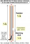
both got 1/4 wave whip antennas whit a decent ground plane on the receiver but on the emissor dont space for a bigger ground plane.

The Basic Code iam using atm whit best results
Emissor
Code:
main:
if pin1 = 1 then
b13 =1
high 5
high 1
pause 60
serout 4,N2400,("UUUUUUXYZ",b0,b1,b2,b3,b4,b5,b6,b7,b8,b9 ,b10,b11,b12,b13)

low 5
low 1
end if

if pin2 = 1 then
b13 =2
high 5
high 1
pause 60
serout 4,N2400,("UUUUUUXYZ",b0,b1,b2,b3,b4,b5,b6,b7,b8,b9 ,b10,b11,b12,b13)

low 5
low 1
end if


if pin0 = 1 then
b13 =3
high 5
high 1
pause 60
serout 4,N2400,("UUUUUUXYZ",b0,b1,b2,b3,b4,b5,b6,b7,b8,b9 ,b10,b11,b12,b13)

low 5
low 1
end if


if pin7 = 1 then
b13 =4
high 5
high 1
pause 60
serout 4,N2400,("UUUUUUXYZ",b0,b1,b2,b3,b4,b5,b6,b7,b8,b9 ,b10,b11,b12,b13)

low 5
low 1
end if
goto main
Receiver
Code:
main: serin 1,N2400,("XYZ"),b0,b1,b2,b3,b4,b5,b6,b7,b8,b9,b10, b11,b12,b13

if b13=1 then
high 2
pause 200
low 2
endif

if b13=2 then
high 4
pause 200
low 4
endif

if b13=20 then
for b0 = 1 to 59999
high 4
pause 59999
next
end if
goto main
the manchester code from hippy sugestion
Code:
main:
b0 = 1
send:
bit15 = bit7
bit13 = bit6
bit11 = bit5
bit9 = bit4
bit7 = bit3
bit5 = bit2
bit3 = bit1
bit1 = bit0
w0 = w0 AND $AAAA
w0 = w0 XOR $AAAA / 2 OR w0
high 5
high 1
pause 100
SEROUT 4,N2400,(170,170,201 ,b1,b0)
pause 100
low 5
low 1
pause 600
goto main
Receiver
Code:
main:
b0 = 5

SERIN 1,N2400,(201),b1,b0
w1 = w0 AND $AAAA
w1 = w1 XOR $AAAA / 2 OR w1

IF w0 <> w1 THEN Error 
bit0 = bit1
bit1 = bit3
bit2 = bit5
bit3 = bit7
bit4 = bit9
bit5 = bit11
bit6 = bit13
bit7 = bit15
 ' Result in b0
 
if b0 = 1 then
high 2
pause 400
low 2
end if
if b0 = 2 then
high 4
pause 400
low 4
end if
goto main

error:
goto main
Tried diferent baud rates but the modules dont like <2400baud.
Would like to ear some opinions how to improve the code for max range.:D
 
Last edited:

hippy

Ex-Staff (retired)
In the original code you send a lot of data bytes which a zero which are unnecessary but do not seem to be causeing a problem.

In the Manchester encoding version that does not send any "UUUUU" pre-amble which may be the problem. The number of U's can vary. Too many should not cause a problem, but too few may.

It is also common to have to send the "UUUUU" pre-amble, then pause, then send the qualifiers and data.
 

i_spyder

New Member
Tried your sugestion and works like a charm.
my test code now looks like

Code:
main:
b0 = 1
send:
bit15 = bit7
bit13 = bit6
bit11 = bit5
bit9 = bit4
bit7 = bit3
bit5 = bit2
bit3 = bit1
bit1 = bit0
w0 = w0 AND $AAAA
w0 = w0 XOR $AAAA / 2 OR w0
high 5
high 1
[COLOR="Red"]SerOut 4, N2400,("UUUUUU")
pause 50[/COLOR]
SEROUT 4,N2400,(170,170,201 ,b1,b0)
pause 100
low 5
low 1
pause 1100
goto main
 

hippy

Ex-Staff (retired)
Glad to hear it's working. That ...

SerOut 4, N2400,("UUUUUU")
pause 50
SEROUT 4,N2400,(170,170,201 ,b1,b0)

sequence seems to be key to good success. Some of the RF code on the forum was written before that was discovered, seemed to work without problems at the time or wasn't rigorously tested.
 

Dippy

Moderator
Excellent.

It's a pity Zizka doesn't get on Forum more often - he is Radiometrix expert. He knows far more about their products than anyone else on this Forum.

Radiometrix have some easy-reading App Notes which may help. (Not for PICAXE programming but general help on radio modules).
http://www.radiometrix.co.uk/apps/apnt000.htm
 

i_spyder

New Member
Dippy Tanks for the link, but ive already read all that stuff and learned alot about rf, i recommend it to any rf enthusiast that haven't read yet, realy good information on those documents.

Iam doing further testing but till now ive tested the following.
Yesterday with the first code full of garbage i was able to make the yellow path with 100% of the data packs received on the other side but on the red one only about 50% was received with the antenna on car top.

Today with dippy code and suggestion iam able to receive 100% of the data packs on the red spot.
Red spot got some 2 or 3 trees beetween the LOS but nothing major and the antenna was on the passager seat.

the rssi on the receiver stop working today for some mysterious reason :mad:

Yellow Spot is 1.5Km away
Red Spot is 1.9Km away

Found a spot today 3.1Km away LOS next to those so gonna test and will post the result later. After that gonna do oversea tests...

Too bad :( i dont have space on the controller for a bigger ground plane, i guess if i did that was able to boost my range even further.
Any suggestions ?
 
Last edited:

manuka

Senior Member
Glad it's working well so far! How "mission critical" (to use a vogue NASA phrase which is sure to annoy Dippy) is this application however? Will false/no triggering be an issue?

You look to already have achieved your range, but for extension (if that vessel is always moored at a certain bearing) a classic Yagi half wave dipole appeals. Even a simple 4 element one at 433 MHz can give 6dB gain (equiv. to range doubling)- the so called "cotanga" version at => http://picaxe.orconhosting.net.nz/yagi433.jpg (which doesn't even bother with impedance matching - OK for reception) is worth rustling up for quick trials. Yagi's are directional, so you'll naturally need to beam it at the signal however.

I've recently been working with 162MHz marine AIS (Automatic Identification Sytem) reception, & had great mileage with 300 Ohm TV ribbon "Slim JIM" antenna. These have a legendary near horizontal pickup that suits vessels at changing bearings on the horizon. With admittedly a sensitive receiver & more powerful transmitter (12 Watts), AIS signals form ships 30 km away (with hills in the way too) have been decoded OK. Stan
 

Attachments

testerrrs

New Member
The Slim Jim is a good idea, here's one I built for the 2m amateur radio band. SWR 1.1 @ 145 MHz. Got everything from local hardware store for about £20 :)
 

Attachments

fizzit

Member
I am looking for a data transmitter/reciever set just like that with a similar output power. Do you know of any US websites that sell them?
 

Dippy

Moderator
fizzit, probably best to contact Radiometrix.
I just did a quick look and found this:-
http://www.radiometrix.co.uk/contact/usa.htm

Obv. antenna style will depend on your application and any physical restrictions, noting possible regulations concerning o/p power and/or gain antennas on the Tx part.

As Stan says, please let us know if the project is Mission Critical and if you have done a Risk Anal-ysis.
 
Last edited:

i_spyder

New Member
sorry for the delay in the response but have been realy busy on the weekend :D.

fizzit check newark and lemos international.

About the antenna on the emissor side needs to be someting portable since is handled so the yaggis and others like it are out of question. guess a 1/2 wave would be better on the emissor since i dont have space for a ground plane but dont know where to buy them at a reasonable price.

my project Ain't mission critical :) or nothing like it, is just a method of comunication between the base on the beach and a boat whit a banana sled, the risks if the system fails are minimal since the lights only to warn the driver when he should stop because the rental time ended and if the people on the banana want a slow / medium / fast speed.
 

manuka

Senior Member
Banana sled rentals! (Check the picture below for those with a sheltered upbringing.) Is the driver your employee? Surely they are not several km off shore like this? Where/how are you intending to mount & water proof the receiver & electronics? Wouldn't a simple & cheap (if drenched) UHF CB voice system would be better? Additionally this'd allow versatile voice comms for rental extensions/sea sick passengers/tow boat or sled problems?

But no doubt language problems are an issue? What do you use at present- hand waving to the tow boat? Although seemingly quaint in a hi-tech age, such hand signals are universally established- even small kids recognise them. SOLAS (Safety Of Life At Sea) is paramount even in shore. Stan (beach side- Wellington,NZ)
 

Attachments

Last edited:

i_spyder

New Member
Usualy the boat navigate about 800m-1km far from the coast. But since iam on the starting point on the shore we have to add the distance from the diagonal, so the distance can increase to 2 3 km most.The electronics will be mounted on a plastic box fully isolated with some silica bags on cockpit's inside, because of the high frequency rf i cant use the potting technic.The elecronics will be feed by the boat 12v battery.

Atm we use cellphone calls but is pointless make 5 calls or so per hour just saying the speed the guys on the banana sled want to go, usualy is slow / medium / fast. And when the rental time gets out, this can be easily replace by 4 lights or probably 3 lights and a buzzer.

UHF CB would be nice as well but that way i wont have a chance to build this and learn something from it. And for an emergency the cellphone will be there. I got 2 guys at least on the boat, one is the driver and the other is looking to the passagers on the sleed for anything that can happen and usualy they always solve it.

and iam thinking in implement this as well on the rentaljetskis
 
Last edited:

manuka

Senior Member
Rental jet skis- which of course can zip out of sight in a flash- it's sounding increasingly commercial. Time we wheeled out the cash register & invoice book ... WHERE ARE YOU - MEXICO?

I've no idea of your local cell phone charges but recommend ~470 MHz UHF CBs for cost effectiveness. These handhelds often sell for as little as US$20 each here in NZ, with ranges across water ~10km. I'm not denying the fun & learning experience of DIY, but am alert to SOLAS. Stan.
 

moxhamj

New Member
My experience with RF comms is that they work well up to a certain range and then data starts getting corrupted. Adding Manchester inproves the range a bit more but not much. It may well be simpler just to put more U's at the beginning and that will get the bias up to 1/2 volts and even if most of the data packet is 0, because the packets are short it shouldn't change the bias. Though if you are just sending very simple things like 'time is up' and 'go faster', you might only need 1 byte. And maybe a checksum! (Stop? We thought you said 'Go Faster'...)

Yagis on the Tx side at 70cm are not very practical I agree. But you can always have a Yagi on the Rx on the shore, and with multi element too.

How about commercial handheld UHF radios but send a very simple system with tones? One beep to go slower. Two beeps to go faster. Three means time is up? Some commercial units already have a button for a beep, and if not, it would be easy to add.
 

i_spyder

New Member
Iam in portugal. and i dont have the experience/ time to make a commercial product, this is for my personal use and fun. And is not a Led or a buzzer that gonna interfer whit solas or whit my country coast guard rules. If for any reason i cant get this to work as i expect i will get a couple of uhf radios but till then ill try my best. anyone know where to buy them online at a decent price in europe?

And dr aculla i use a checksum on my code as you can see on the first post. Iam using 868mhz so the band is 32cm i think. But thanks for your ideia , i guess with a DTMF encoder decoder and some uhf radios will be better and simpler than the way iam doing
 
Last edited:

Dippy

Moderator
Have you done any tests on ignition (electrical) noise interfering with radio signal?

If it is bad, then you could Manchester until the cows come home and it wouldn't help.
Manchester <> Magic ;)
An alarm clock on the boat might be more reliable.
 

MFB

Senior Member
My radio experience is mostly confined to telemetry from race cars going around a track but it sounds like your basic requirements are much the same. I found that FSK modulation provided the best results in the presents of high levels of ignition interference. A Km ranges could be acheived using only a few hundred mW with not directional transmitter and receiving antennas. The information provided in my recent 'Narrow-band radio telemetry' posting on the User Projects-Communication section would allow you to try standard (in on the mic and out of the speaker) low cost walkie-talkies to send data at 1200 bps. However, it my not be legal in all countries to use this type of equipment to send data.
 

manuka

Senior Member
MFB: FSK is certainly superior to ASK with impulse noises. Good insights, & I've been a packet radio fan in the past, but those chips you mention are now almost unobtainable (& ~US$10 each when cornered too). I put considerable thought into this ~2006 while trying to work within the crazy Australian "3 seconds an hour" UHF CB data regs. Stan
 

MFB

Senior Member
Stan, Its true that it has become increasingly difficult to find slow FSK modem chips since the demise of dial-up computer links. The Texas Instruments TCM3105 became extinct many years ago but I didn’t know that the same fate had befallen the FX614 from Consumer Microcircuits Ltd. However, it has been a couple of years since I last purchased a batch.

Do you know of any suitable single chip FSK modems that are readily obtainable? Ideally, it would be good if these devices had the option of operating at even lower (than 1200bps) data rates for those interested in topics like long distance balloon telemetry.
 

manuka

Senior Member
Both FSK modem & DTMF chips from the good old days are now pretty much obsolete, & hence elusive/costly. The industry has predictably moved to micro emulation or some fire breathing but cryptic ASIC (Application Specific ICs). While this may be OK for those with 1,000 up needs, it's frustrating for enthusiasts. See the likes of the nifty CMX865 ( which in bulk is only ~US$2) => http://www.cmlmicro.com/products/datasheets/Docs/cmx865ds.pdf

Several of us have pondered PICAXE produced DTMF,which for this banana boat may have appeal. Stan

EXTRA: An idle email (while I penned this) to a Hong Kong stockist of the CMX865, has been promptly answered! They'll sell those CMX865 for US$8 each 10 up, falling to US$1.19 100,000 up. Any starters out there?
 
Last edited:

MFB

Senior Member
Stan, Thanks for the link to the CMX865. Regarding your comment about PICAXE produced DTMF, I was wondering if it would be possible to generate an FSK output. It has been done with a 4Mhz PIC using a simple 3-resistor DAC and assembler code but maybe a fast 20-X2 would also be upto the task. At least for 110 or 300 bps?
 

manuka

Senior Member
Such dual audio tone frequency shifting (hence AFSK) is a regular PICAXE ponder ( see the likes of =>http://www.picaxeforum.co.uk/archive/index.php/t-7701.html). It's beer o'clock here so I'll pass on the calculations, but previous penciling had not been hopeful. Yes- maybe the 20X2!

I'd actually pondered it with the 433 MHz ISM units, as they're capable of rapid tone shifts. However ENCODING & DECODING the tones may swamp the 256 bytes "M" PICAXE memory.
 

MFB

Senior Member
Simple FSK modulator

The attached schematic shows a low cost and smaller alternative to using the FX614 modem chip. This Schmitt based circuit has provided good results when used with the RF Solutions 433MHz pair that is sold for £9.99 in the UK by Maplin Electronics Ltd. Although I retained an FX614 between the receiver output and PC serial input, this chips function could have been performed by a sound card and filter/demodulator software.

The trimmer needs to be adjusted to provide, as near as possible, the two FSK tones of 1200 Hz and 2200 Hz. The FSK decoder can also be used with an audio link by adding the output attenuator shown and adjusting for best results at the receiver output.
 

manuka

Senior Member
The original 300 bps AFSK "Kansas City" mid 1970s standard, used to store programs onto cassette tape, recorded data as "marks" (one) and "spaces" (zero). A mark bit consisted of eight cycles at a frequency of 2400 Hz, while a space bit consisted of four cycles at a frequency of 1200 Hz. Classic "jingle bells" RTTY (radio teletype) - which was at it's zenith in the 1930-40s - however used both narrower shifts & slower baud rates (~50 baud) => http://en.wikipedia.org/wiki/Radioteletype Such pedestrian speeds should be "doable" with PICAXE encoding, especially if the simpler Baudot/Murray Code is used.

In more recent times (but still back ~5 years), I recall testing AFSK 1200-2400bps bare bones component level encoding circuitry with poor results. Holding those 2 freqs. tightly related to PSU & cap. values that didn't wander. You could get one, but not the other! Issues with oscillations that didn't (or maybe it was DID) instantly switch (mid cycle) arose as well. If PICAXEd this may be a PWM issue? See => http://content.answers.com/main/content/img/CDE/_FSK.GIF

Hippy: PICAXE PWM indeed appeals, & it may just be able to handle 300bps- or slower. Worth sharpening the pencil for some calculations maybe.

However,all up, dedicated modem ICs are far more appealing - but now annoyingly ELUSIVE. I've even stooped to rescuing some from phone caller ID 1200bps units. Stan.
 
Last edited:

premelec

Senior Member
Stan - what chip do you find in the caller ID box? I have several of those old stand alone with 2 AA battery types... but hadn't looked inside... thanks -

Also I've seen PLL chips locked to incoming tone and using the voltage to shift their lock VCO frequency as the digital output - not super fast but we're talking slow here... seems like the market has gone to maximum rates rather than low power slow rates.
 

manuka

Senior Member
Premelec: Mine came from a standalone Oricom Caller ID unit ~6 years back & has long since moved on. I've the schematic somewhere however. Check others findings at sites such as => http://www.raphnet.net/electronique/cid/cid_en.php

The classic NE567 PLL single tone decoder crossed my mind too, but it's decades old & it almost seems to be admitting DTMF/AFSK defeat if used! But at least they seem still available - & cheaply ( < US$1 ) too. FWIW I recall being first 567 enthused by late 1970s articles penned by the illustrious Forrest M.Mims III.
 
Last edited:

MFB

Senior Member
Hippy, I needed 1200bps to send accelerometer data from a model rocket and did not think this rate would be possible using PWM. Was I correct in this assumption?

BeanieBots, Same with the sound command. The reason the input is on the right is that the attachment was cut from a larger schematic of the instrumentation payload.

Stan, Having initially thought that crystal accuracy was required, I was pleasantly surprised by the results obtained from the simple FSK modulator. Using a regulated supply and polycarbonate capacitors seems to provide adequate stability for use with the FX614. Even though the output from the receiver is a pretty poor approximation of a sign-wave, and different in amplitude between the tones, it was possible to maintain a robust data link over a range of several hundred metres (using the low-power 'Maplin pair').

Of course I would not recommend this approach for a ‘product’ as a FX614 would offer better performance. However, if you are low on space (and funds) for your next narrow-band telemetry project, it might be worth investigating the simple modulator.
 

hippy

Ex-Staff (retired)
Hippy, I needed 1200bps to send accelerometer data from a model rocket and did not think this rate would be possible using PWM. Was I correct in this assumption?
I cannot say for sure, but 2400 baud is 416us per bit, all a PICAXE needs to do is read an input line and choose one of two PWM frequency and duty options. A PICAXE-X2 at high-speed may be fast enough to track the baud rate.
 

MFB

Senior Member
Hippy, The PICAXE-14M that I was using for rocket instrumentation also had to scan five ADC channels and three digital inputs at 15Hz. Not just read an input line and decide on which PWM output frequency to generate.

However, the 20X2 would be quite another matter. It might even be able to generate an eight segment sine-wave FSK signal by using three output lines and resistors to form a DAC. All a bit beyond my software skills though!
 

hippy

Ex-Staff (retired)
I was presuming a PICAXE to be dedicated to just reading an input and generating output as a replacement for an FSK chip - There's only so much a PICAXE can do !

Some of the PICmicros ( X1, X2, X2-3V ) have a voltage reference generator which can be routed to an external pin to generate a 16-level DAC ( 32 on 20X2 ). Poking the SFR may however be slower than outputting a bit pattern to an external DAC. Don't know if the routing works on all PICAXE's but did on whichever I tested - I forget which one.
 

BeanieBots

Moderator
Some of the PICmicros ( X1, X2, X2-3V ) have a voltage reference generator which can be routed to an external pin to generate a 16-level DAC ( 32 on 20X2 ). Poking the SFR may however be slower than outputting a bit pattern to an external DAC. Don't know if the routing works on all PICAXE's but did on whichever I tested - I forget which one.
That could be a really useful feature.
Would be nice if you could remember.
 

hippy

Ex-Staff (retired)
28X2 (5V) ...

Code:
#Picaxe 28X2
#Terminal 9600
#No_Table

' Link Leg 2 (ADC0) to Leg 4 (CVREF)

Symbol CVRCON = $B5

Do
  For b0 = %11000000 To %11001111
    PokeSfr CVRCON, b0
    Gosub CheckAdc
  Next
  For b0 = %11001110 To %11000001 Step -1
    PokeSfr CVRCON, b0
    Gosub CheckAdc
  Next
  SerTxd( CR, LF )
  Pause 1000
Loop

CheckAdc:
  ReadAdc10 0, w1
  SerTxd( #w1, " " )
  Return
 
Last edited:

hippy

Ex-Staff (retired)
Also works on 40X2-5V, 28/40X2-3V, and 28/40X1 ( Poke VRCON,b0 / Symbol VRCON=$97, everything else as above ).

Would expect it to work on 20X2 but a little more complicated and involved as CVREF is on Serial Out ( datasheets indicates CVREF overrides the digital output ) and there are a lot more SFR's to configure ( only one SFR to poke to change voltage though ).

The big surprise was the 18X works ( Poke VRCON,b0 / Symbol VRCON=$9D, link Leg 1 to Leg 17, otherwise as above ).

The 08M, 14M and 20M have the CVREF but not routed out, 18M does not have it. For all the PICAXE's which route it out, note the comments about buffering in the datasheets.
 

MFB

Senior Member
Low-Power 433MHz Telemetry System

I managed to dig up more information about the 433MHz low-power FSK rocket telemetry system that I developed a couple of years back. As it is by no means capable of ‘long range’ I have posted it under the Communications User-Projects section
 
Top