Hi, I am referring to the line tracker module. On page 11, there is a picture of the module, and it says
"Ensure the Line Tracker module is the correct way up and fit one of the brics to the top of circuit board."
The board in the manual didn't have the same look from the one I received.
Please advise which way the correct way up for my board is.
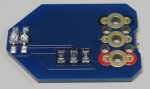
The board I received has a different look from the diagram with one side labelled 'Line Tracker'
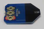
and the other side unlabelled.
"Ensure the Line Tracker module is the correct way up and fit one of the brics to the top of circuit board."
The board in the manual didn't have the same look from the one I received.
Please advise which way the correct way up for my board is.
The board I received has a different look from the diagram with one side labelled 'Line Tracker'
and the other side unlabelled.