Hello again, this is another one in reference to a tank I'm making.
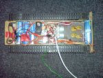
It is basically a model tank, that has been converted to remote control using aircraft RC gear.
I recently stripped it out though to start again, as I had added on so much stuff that it would be better to retry with all new improvements in mind from the start.
The whole system would run on 5V quite well:
Receiver = 4.8v - 6v
PICAXE = 3v - 5.5v
Motors = 0v - 6v
My previous design used a load of 1.2v NiMH batteries but they only gave 1400mAh. I have now found a li-poly pack that gives 6Ah - much more like it.
The problem is that, being li-poly, it only gives 3.7V.
What would be the best way to bring this to 5V?
Can li-polys be put in series (I suspect not and wouldn't try it unless sure)?
Would this step-up module be able to supply two hungry motors?
 hence the "perhaps" and "may"