westaust55
Moderator
Having got my CMPS03 re-calibrated manually (no luck with the i2c method)
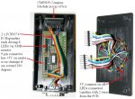
I have assembled the CMPS03 into a small plastic box, mounted on the inside top with nylon nuts and bolts.
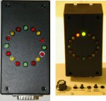
On the cover of the box, I have assembled a circle of 16 LED's as a form of simple visual heading indicator. These LED's are controlled via two PCF8574 8-bit IO expanders - each controlling 8 LED's.
Tonight, I have successfully written a short program to drive the 16 LED's in 32 steps corresponding to the compass heading. Again I have used a maths based scheme (akin to my earlier bargraph logic) rather than the look-up table in EEPROM as often done.
Attached is a diagram showing how the LED patterns are used for 32 steps with a resolution of 11.25 degrees and below is a sample of the code I wrote to drive the LED's.
hmmm, I guess a Nokia 3310 graphic LCD screen would also make a nice compass heading display as well - likely even better angular resolution as well. Food for thought and future projects here.
I have assembled the CMPS03 into a small plastic box, mounted on the inside top with nylon nuts and bolts.
On the cover of the box, I have assembled a circle of 16 LED's as a form of simple visual heading indicator. These LED's are controlled via two PCF8574 8-bit IO expanders - each controlling 8 LED's.
Tonight, I have successfully written a short program to drive the 16 LED's in 32 steps corresponding to the compass heading. Again I have used a maths based scheme (akin to my earlier bargraph logic) rather than the look-up table in EEPROM as often done.
Attached is a diagram showing how the LED patterns are used for 32 steps with a resolution of 11.25 degrees and below is a sample of the code I wrote to drive the LED's.
Code:
; =================================================
;   File....... CMPS03 LED heading Indicator Test
;   Purpose.... test operation of the set of 16 LEDs via i2c comms
;   Author..... Westaust55
;   E-mail.....
;   Started.... 02-07-2008
;   Updated.... DD-MM-YYYY
;  ===============================================
;
; -----[ Program Description ]---------------------------------------------
;
; A program to test operation of the set of 16 LEDs mounted in a circle
; as a visual heading indication for use with the CMPS03 cpompass module
; using i2c comms
;
; -----[ Revision History ]------------------------------------------------
; First coding
;
;
; -----[ I/O Definitions ]-------------------------------------------------
;
;
; -----[ i2c Devices ]-------------------------------------------------------
;

;
; PCF8574 8-BIT IO EXPANDERS
SYMBOL expand_0 = %01000000  ; %0100 = Chip ID, 000 = Addr 0 - For the 8 Red LED's
SYMBOL expand_1 = %01000010  ;                , 001 = Addr 1 - For Keypad Shift LED
SYMBOL expand_2 = %01000100  ;                , 010 = Addr 2 - For Compass LED display right half
SYMBOL expand_3 = %01000110  ;                , 011 = Addr 3 - For Compass LED display left half
;
;
; DS1338 REAL TIME CLOCK with 56 bytes of RAM
SYMBOL rtc1338  = %11010000  ; %1101 = Chip ID, 000 = hard addr
;
;
; -----[ Constants ]-------------------------------------------------------
;
;
; -----[ Variables ]-------------------------------------------------------
;
SYMBOL delaytime = b22
SYMBOL pattern   = w10
SYMBOL pattrn2   = w9
;
; -----[ EEPROM Data ]-----------------------------------------------------
;
;
;
; -----[ Initialization ]--------------------------------------------------
;
Init:   delaytime = 500

;
;
; -----[ Program Code ]----------------------------------------------------
;
Main:	  HI2CSETUP i2cmaster, expand_1, i2cslow, i2cbyte ; Set up for 9th LED
        HI2COUT (0) ; SHIFT LED off
        PAUSE 500
        HI2COUT (1) ; SHIFT LED on - just blink LED on and off
        PAUSE 1000
        HI2COUT (0) ; SHIFT LED off
        PAUSE 500
        HI2CSETUP  i2cmaster, expand_0, i2cslow, i2cbyte ; Set up for set of 8 LEDs
        HI2COUT (255) ; turn on all LEDs for 1 second
        PAUSE 1500
        HI2COUT (0)
        PAUSE delaytime

; the above line of code are just to turn of the LED's for the bargraph and keypad shit key
; these LED's use positive logic (1 = ON, 0 = OFF) done by adding a transistor to the expander outputs.
;
;
; the LED's for the compass heading are wired and using inverted logic
; hence the INV command at the start of the shwpattn subroutine below.


circle: FOR w4 = 0 TO 359     ; degrees in circle

        w5 = w4 * 10          ; this is equal to actual reading will get from CMPS03
        w2 = w5 * 10 + 562    ; adjusted value 562 = half of the 11.25 degree resolution as offset
        w2 = w2 / 1125 AND 31 ; divide by 11.25 deg reolution for step 0 to 31 and rolling over to 0
        b6 = w2 / 2           ; bit position for the first LED posiiton 0 to 15
        b7 = w2 // 2          ; when b7 = 1 means the 2nd LED is required

        IF b7 = 1 THEN
          b7 = b6 + 1         ; get the corect bit position for the 2nd LED
        ENDIF

        pattern = DCD b6      ; 1st LED is encoded here

        IF b7 > 0 THEN
          pattern = DCD b7 OR pattern ; add/or in bit position for second LED when it is required
        ENDIF

        GOSUB shwpattn        ; now display the correct LED pattern

        PAUSE 100

        NEXT w4               ; advance to next degree of heading

        GOTO circle           ; and go around again and again

;       END
;
; -----[ Subroutines ]----------------------------
;
shwpattn: pattrn2 = INV pattern
          HI2COUT [expand_2], (b18)  ; pattern for right side of LED indicator
          PAUSE 10
          HI2COUT [expand_3], (b19)  ; pattern for left  side of LED indicator
          RETURN
;
; -----[ Interrupt Routines (if used) ]-----------
;
;Interrupt:
;
;         RETURN
; =================================================
;      THE END
; =================================================
hmmm, I guess a Nokia 3310 graphic LCD screen would also make a nice compass heading display as well - likely even better angular resolution as well. Food for thought and future projects here.
Attachments
-
28.5 KB Views: 100
Last edited:
 ) then modified BASIC to add SET and RESET commands to turn each “chunk” (2x2 pixels). Fun was as much doing the maths in M/C to be able to alter any one chunk without affecting any other chunk using additional character graphics by burning a new and larger EPROM as character graphic generator.