Can someone tell me how to control the display?

 www.pollin.de
It only has 4 connections: GND, VCC, Data, Clk
www.pollin.de
It only has 4 connections: GND, VCC, Data, Clk
The two 4 x 7 digits displays are addressed via two shift registers 74HC164 but I can't find anywhere how to address a specific display.
Greetings
Wolfgang
Digitalanzeige Modul DAYPOWER LC-Display-Dig-2R
Mit dieser Platine erhalten Sie eine Doppel LED-Anzeige mit je 4 Digits. Sie wird über serielle Schnittstellen angesteuert. Ideal zur Anzeige einer Uhrzeit, Stoppzeit oder zur Darstellung von Messwerten. Nur in Verbindung mit einem steuerndem
www.pollin.de
The two 4 x 7 digits displays are addressed via two shift registers 74HC164 but I can't find anywhere how to address a specific display.
Greetings
Wolfgang
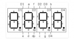
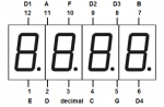
![3461BS[1].png](/data/attachments/19/19856-16ec4c59df82f2b861a3b5050fe6bc6f.jpg)
") I had "expected" common-cathode and/or NPN digit-driver transistors as being the most "favourable", but could there be any "hidden" PNPs ? These were my thoughts last night which might still have some relevance:
I had "expected" common-cathode and/or NPN digit-driver transistors as being the most "favourable", but could there be any "hidden" PNPs ? These were my thoughts last night which might still have some relevance: