IRL540? (motor driver circuit

atarian

New Member
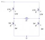
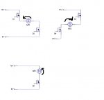
Hi i fairly new to picaxe and built a board to run a 12v dc motor using a 12vdc 2.5A power supplie i scrounged from some where and i then built a board using 4 IRL540s to control direction but it didn't work
does a PICAXE output pin have enough grunt to run to IRL540s ?

thanks in advance

Atarian
 

Andrew Cowan

Senior Member
The IRL540 datasheet says they need Vgs=5 (voltage between the gate and source needs to be 5). The picaxe can give this if the source is connected to 0V. As long as you are not PWMing them, and it is just on/off, they need very little current to work, so no problems here.

Note the 5V is between gate and source - are you providing this in the upper two? I think that you would need 17V on the gate as you are using them as a high side switch, meaning the source is connected to 12V effectivly. I'll draw a schematic.

Andrew
 

Attachments

Last edited:

marcos.placona

Senior Member
Why don't you just use a driver for that, such as the LM293? It makes life so much easier, and you don't need to have 4 transistors to control that. Everything is on one IC, and can control up to 2 motors.
 

Andrew Cowan

Senior Member
LM239D has a maximum motor current of 600mA. I don't know how much Atarian's motor draws, although the 2.5A power supply suggests it draws about 2A. 12V motors are usually pretty big - I would expect it to draw at least 1A under load.

The L298 might be a better option than the LM239D - it can power 2 motors of 2A each (up to 46V).

Andrew
 

atarian

New Member
Thanks for the great replies yeah the motors draw 2A and i can see from you image where i went wrong i think i am going to change the design to accomadate that using just the two mosfet on the ground instead of all four

Thanks for your help
 

Dippy

Moderator
Atarian,
Please post your schematic.
I'm stretching as much as I can... but, no, I can't quite see how you've wired it from here.
 

Andrew Cowan

Senior Member
i think i am going to change the design to accomadate that using just the two mosfet on the ground instead of all four
That won't work.

The idea of the H bridge (with 4 FETs), is that if you turn the top right and the bottom left on, the motor will go one way. If you turn the bottom right and top left on, it will go the other way. You only ever have 2 on at one time - one at the top, and one at the bottom on the opposite side.

If you do not want direction control, then you can use just 1 FET at the bottom, and permanantly connect the top side.

Alternativly, if you don't exceed 2A, use the L298 driver.

Andrew

The attached schematic shows the H bridge in its two directions (top pictures), and the method that doesn't give you directional control (using 1 FET).

In the top two pictures, the FETs that are off are not shown.
 

Attachments

Last edited:

atarian

New Member
i was quite thinking straight when i posted that post yeah i can see where you are confused , is there another type of mosfet i could use in the upper mosfets in the power bridge that the picaxe could run easily. if not i will probably go with the L298

just so veryone knows i am using a PCB so it's hard to change which is why i don't really won't to use the L298

thanks again everyone
 

atarian

New Member
i know i shouldn't really have double posted so soon but i was wondering if anyone had an example of a L298 motor driver in combination with a picaxe chip
 

Dippy

Moderator
You can use suitable P chan MOSFETs for the high-sided part.

Are you doing speed control as well?

And if you are PWMing do have a search over the past few weeks a a good amount of info on MOSFET driving has been provided.

Oh for a Piki...
 

Andrew Cowan

Senior Member
I thought P channels might have something to do with it, but I wasn't sure.

I have used the l298 before with success.

As you already have the PCB, it might be easier to use P channel FETs. However, in the long run, I would use the L298, as it includes the drivers needed to run the FETs if you want to PWM them for variable speed. It also does not have the danger that an H bridge does - in an H bridge setup, if you turn on both the top and bottom FETs on one side, you short circuit through the FETs, which could damage them if the currents are high.

With the L298, you can also join the outputs together to get a 4A switching device, instead of two 2A ones.

Andrew
 
Last edited:

atarian

New Member
i am not planning to use speed control as the motor only has to lift something up then out it back down again so it's pretty simple
 
Top