Interactive Menu Help

Mad Professor

Senior Member
Good Day All.

I have been playing with PicAxe for some time now, only basic stuff.

I have now given my self a new project, and I am not sure where to start with the code, so I hope that you guys can help me out.

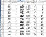
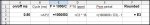
I want to build a little box to Generate pulses from 0.50 to 1.50ms in 0.05ms steps with a LCD Display and Interactive Menu.

I already have a box without LCD Display or Menu, when it's powered up it just pulses 3ms for (x)time then 6ms for (x)time, and so on upto 12ms, then stops.

If possible I would like to use a 20x2 LCD Display from TechSupplies, and four press buttons to access the menu, (Select, Cancel, Left, Right).

When the unit is powered up I would like it to do the following.

Display
Manual Control
Automatic Control

Manual Control
Pulse: 1.50ms 50% DC
------------------Run

Automatic Control
Start Range: 0.50ms
-----------------Next
--------------------
End Range: 1.50ms
------------------Run


As I have not worked with LCD displays or any kind of Interactive Menus I need your help and advice on where to start.

Hardware should not be a problem for me, it's just the coding I am going to have problems with.

Here is the code I use for my current test box.
Code:
symbol Start_LED = 0		‘
symbol Stop_LED = 1		‘
symbol Pump = 2			‘
symbol Inj_1 = 3		‘
symbol Inj_2 = 4		‘
symbol Inj_3 = 5		‘
symbol Inj_4 = 6		‘

Main:				‘

low 0,1,2,3,4,5,6,7		‘ All Outputs Off.
high Start_LED			‘ Start Button LED On.

if pin6 = 1 then C_30	‘
goto main

C_30:			‘
low Start_LED			‘ Start Button LED Off.
high Stop_LED			‘ Stop Button LED On.
for b2 = 1 to 45		‘ Loop whole lot 45 times (~30 mins)
for w0 = 1 to 1666		‘ define loop for 1666 times (10 sec)
high Inj_1,Inj_2,Inj_3,Inj_4	‘ Injector Bank 1,2,3,4 On.
pause 3				‘ Pause for 3ms.
low Inj_1,Inj_2,Inj_3,Inj_4	‘ Injector Bank 1,2,3,4 Off.
pause 3				‘ Pause for 3ms.
next w0				‘ end of loop.
w0 = 0				‘ 
for w0 = 1 to 833		‘ define loop for 833 times (10 sec)
high Inj_1,Inj_2,Inj_3,Inj_4	‘ Injector Bank 1,2,3,4 On.
pause 6				‘ Pause for 6ms.
low Inj_1,Inj_2,Inj_3,Inj_4	‘ Injector Bank 1,2,3,4 Off.
pause 6				‘ Pause for 6ms.
next w0				‘ end of loop.
w0 = 0				‘ 
for w0 = 1 to 555		‘ define loop for 555 times (10 sec)
high Inj_1,Inj_2,Inj_3,Inj_4	‘ Injector Bank 1,2,3,4 On.
pause 9				‘ Pause for 9ms.
low Inj_1,Inj_2,Inj_3,Inj_4	‘ Injector Bank 1,2,3,4 Off.
pause 9				‘ Pause for 9ms.
next w0				‘ end of loop.
for w0 = 1 to 416		‘ define loop for 416 times (10 sec)
high Inj_1,Inj_2,Inj_3,Inj_4	‘ Injector Bank 1,2,3,4 On.
pause 12			‘ Pause for 12ms.
low Inj_1,Inj_2,Inj_3,Inj_4	‘ Injector Bank 1,2,3,4 Off.
pause 12			‘ Pause for 12ms.
next w0				‘ end of loop.
next b2				‘ 
low Stop_LED			‘ Stop Button LED Off.
goto main
Thanks for your time.

Best Regards.
 
Last edited:

hippy

Ex-Staff (retired)
high Inj_1,Inj_2,Inj_3,Inj_4 ‘ Injector Bank 1,2,3,4 On.
pause 3 ‘ Pause for 3ms.
low Inj_1,Inj_2,Inj_3,Inj_4 ‘ Injector Bank 1,2,3,4 Off.
A few things there -

When setting multiple lines high / low / toggled they will not all switch at the same time. Using multiple pins in such a command is really just shorthand for specifying multiple sequential commands on single pins. You can use "pins=" to set all pins as near simultaneously as possible.

Taking into account the time to turn on and off lines, the entire pulse period will not be exactly as specified. You would be better off using the PULSOUT command or perhaps PAUSEUS for those PICAXE's which support it.

To control the pulse time, and resolution to 50us, could require some tweaking. A solution there may be to run at the fastest clock speed and extend timing periods as required.
 
Last edited:

Mad Professor

Senior Member
Thanks for your replys so far.

I am testing for Fuel Injector Opening Rates.

Most injectors I have tested have a Opening Rate from 0.80ms to 1.20ms, but I have seen as low as 0.50ms and as high as 1.50ms.

I used to use a ECU in test mode to send pulses to the injectors for testing, but this means I need a Power Supply, ECU, Laptop, Scope, Injectors ,ect all on my work bench at the same time.

With my current setup I still have alot of stuff on my bench, With the new design I hope to make it all most portable, or at least less stuff on my work bench.

I have a 0.010ohm resistor in-line of the switched side of the injector, I then tap each side of the resistor with the scope to watch the current load, then run the test box and watch to see at what pusle rate the injector current peaks at, then I know it's opening time.

I am sure with my current project I could even do away with monitoring with the scope and get the picaxe to tell me the peak current of the injector.

But I have not looked into this yet.

To date I have only used the PicAxe 18X chip in all my other project, but I don't have any problem going for a smaller or bigger chip to aid the progress of this project.

I have given my self a bugit of around £45-50 to buy all the parts needed and built the new test box.

Thanks for your time.

Best Regards.
 

eclectic

Moderator
@MadProf.

Just some vague garbled ideas to try, using your 'scope.
It is not meant as a finished version, just work in progress.

This program produces frequencies between ~ 1kHz to 333 Hz.
I used a 28X1, but it should work with your 18X.
If it does, you could connect the Pwmout to four output via say, a ULN2803.
Code:
#picaxe 28x1

symbol freq = w1
symbol duty = w2

main:
for freq = 58 to 188 ; PWMOUT ~16000 to ~ 320 ish

duty = freq *2 ; 50% duty

pwmout 1 , freq , duty 
 ;change to pwmout 3 for 18X
 
peek $12,b1
b1 = b1 +2
poke $12, b1  
; magic spells to divide pwmout by 16 !!


pause 1000
next

goto main
Original idea courtesy of Dippy.
http://www.picaxeforum.co.uk/showthread.php?t=5872&highlight=jeremy+pwm*

e (and OE)
 

eclectic

Moderator
@MadProf
I've changed my code above to an 18X
The output from pin3 goes to
Input pin 1 and to the oscilloscope.

It shows 50% duty over the frequency range you need.
(If I've got the sums right.)
They do not, however, conform to the 0.05ms spacing.

Moving to a 28X1, with 11 inputs,
it should be possible to use three input pins each to control frequency and Time-on.
Up : Down : Confirm.
Then, progress to a menu system.


Code:
#picaxe 18x

symbol alter = 6
symbol PWfreq = w1
symbol PWduty = w2
symbol ppsec = w3

main:
for PWfreq =  61 to 188 
; Initial  PWMOUT ~16000 to ~ 5333 ish
; Final    PWMOUT ~1000 to ~ 332 ish

PWduty = PWfreq *2 +1 ; 50% duty

pwmout 3 , PWfreq , PWduty 
 

poke $12, alter ;b1  

count 1,1000,ppsec

sertxd ("Pwm = ",#PWfreq, "  count = ",#ppsec,cr,lf)

next
goto main
Have you got the AXE033 yet?

e
 

Mad Professor

Senior Member
eclectic: Thanks for your replys.

I do have a few spare 18x chips that I can use for testing the code.

I have not yet brought any of the hardware for this current project yet as I wanted to start with the code 1st.

If you say said chip will be the best one for this project I will go with that and order one, if you say said display is better suited I will go with that also, as long as my send does not go parts £45-50.

I have just got rid of my old desk scope and replaced it with a USB PicoScope.

So I'll have a play with the code snips you have given me so far.

Thanks for your time,
 

eclectic

Moderator
@MadProf

Don't spend any cash yet.
Have a play with the second code, and use your 'scope
to measure the frequencies.

What sort of board are you planning?

1. Veroboard.
2. Using an 18X project board.

or other?

e
 

Mad Professor

Senior Member
I have tested your 2nd code on my 18x

here are some of the readings (Average).

--------------------------------------------------------------------
61 / 123 = 1.008KHz / 491.8us High / 499.8us Low @ 49.60% Duty Cycle.
62 / 125 = 992.4Hz / 499.8us High / 507.8us Low @ 49.60% Duty Cycle.
63 / 127 = 976.8Hz / 507.8us High / 515.8us Low @ 49.61% Duty Cycle.
64 / 129 = 961.8Hz / 515.8us High / 523.8us Low @ 49.61% Duty Cycle.
65 / 131 = 947.2Hz / 523.8us High / 531.8us Low @ 49.62% Duty Cycle.
66 / 133 = 933.1Hz / 531.8us High / 539.8us Low @ 49.63% Duty Cycle.
67 / 135 = 919.4Hz / 539.8us High / 547.8us Low @ 49.63% Duty Cycle.
68 / 137 = 906.1Hz / 547.8us High / 555.8us Low @ 49.64% Duty Cycle.
69 / 139 = 893.1Hz / 555.8us High / 563.8us Low @ 49.64% Duty Cycle.
70 / 141 = 880.5Hz / 563.8us High / 571.8us Low @ 49.65% Duty Cycle.
71 / 143 = 868.3Hz / 571.8us High / 579.8us Low @ 49.65% Duty Cycle.
--------------------------------------------------------------------
178 / 357 = 349.3Hz / 1.428ms High / 1.436ms Low @ 49.86% Duty Cycle.
179 / 359 = 347.3Hz / 1.436ms High / 1.443ms Low @ 49.86% Duty Cycle.
180 / 361 = 345.4Hz / 1.443ms High / 1.452ms Low @ 49.86% Duty Cycle.
181 / 363 = 343.5Hz / 1.452ms High / 1.460ms Low @ 49.86% Duty Cycle.
182 / 365 = 341.6Hz / 1.460ms High / 1.468ms Low @ 49.86% Duty Cycle.
183 / 367 = 339.8Hz / 1.468ms High / 1.475ms Low @ 49.87% Duty Cycle.
184 / 369 = 337.9Hz / 1.475ms High / 1.483ms Low @ 49.87% Duty Cycle.
185 / 371 = 336.1Hz / 1.484ms High / 1.492ms Low @ 49.87% Duty Cycle.
186 / 373 = 334.3Hz / 1.492ms High / 1.500ms Low @ 49.87% Duty Cycle.
187 / 375 = 332.5Hz / 1.500ms High / 1.507ms Low @ 49.87% Duty Cycle.
188 / 377 = 330.8Hz / 1.507ms High / 1.515ms Low @ 49.87% Duty Cycle.
--------------------------------------------------------------------
 
Last edited:

eclectic

Moderator
MadProf.
I did a spreadsheet of the 21 values you need.
I've changed the code a little, but haven't yet got round to full commentary.

Your results may be different from mine,
due to Picaxe speed variations.

I'd be interested to see your results.

e
Code:
;Picaxe 15/16 0108 Madprof
#picaxe 18x

symbol alter   = 6 ;MIGHT need changing
symbol Pfreq   = b2
symbol Pchoose = b3
symbol PWduty  = w2
symbol ppsec   = w3

main:
; steps through each of the 21 output values.
for Pchoose =  0 to 20 
lookup Pchoose ,(62,68,74,80,87,93,99,105,112,118,124,130,137,143,149,155,162,168,174,180,188), Pfreq

PWduty = Pfreq *2 +1 ; 50% duty

pwmout 3 , Pfreq , PWduty 
 

poke $12, alter 
pause 1000
count 1,1000,ppsec

sertxd ("Value position :",#pchoose,"  Pwm = ",#Pfreq, "  count/s = ",#ppsec,cr,lf)
pause 5000
next
goto main

; based on Spreadsheet values for 0.50 >> 1.50 ms pulson/pulsoff in 0.05 steps 
;(62,68,74,80,87,93,99,105,112,118,124,130,137,143,149,155,162,168,174,180,187)
;can be tweaked
 

Mad Professor

Senior Member
I have just tested your latest code.

--------------------------------------------------------------------
062 / 125 = 992.3Hz / 499.9us High / 507.9us Low @ 49.60% Duty Cycle.
068 / 137 = 905.9Hz / 547.9us High / 555.9us Low @ 49.64% Duty Cycle.
074 / 149 = 833.5Hz / 595.9us High / 603.9us Low @ 49.67% Duty Cycle.
080 / 161 = 771.8Hz / 643.9us High / 651.9us Low @ 49.69% Duty Cycle.
087 / 175 = 710.4Hz / 699.9us High / 707.9us Low @ 49.72% Duty Cycle.
093 / 187 = 665.0Hz / 747.9us High / 755.9us Low @ 49.73% Duty Cycle.
099 / 199 = 625.1Hz / 795.8us High / 803.9us Low @ 49.75% Duty Cycle.
105 / 211 = 589.7Hz / 843.9us High / 851.9us Low @ 49.76% Duty Cycle.
112 / 225 = 553.2Hz / 899.8us High / 907.8us Low @ 49.78% Duty Cycle.
118 / 237 = 525.3Hz / 947.8us High / 955.8us Low @ 49.79% Duty Cycle.
124 / 249 = 500.1Hz / 995.9us High / 1.004ms Low @ 49.80% Duty Cycle.
130 / 261 = 477.2Hz / 1.044ms High / 1.052ms Low @ 49.81% Duty Cycle.
137 / 275 = 453.0Hz / 1.100ms High / 1.108ms Low @ 49.82% Duty Cycle.
143 / 287 = 434.1Hz / 1.148ms High / 1.156ms Low @ 49.82% Duty Cycle.
149 / 299 = 416.8Hz / 1.196ms High / 1.204ms Low @ 49.83% Duty Cycle.
155 / 311 = 400.7Hz / 1.244ms High / 1.252ms Low @ 49.84% Duty Cycle.
162 / 325 = 383.5Hz / 1.300ms High / 1.308ms Low @ 49.85% Duty Cycle.
168 / 337 = 369.9Hz / 1.348ms High / 1.356ms Low @ 49.85% Duty Cycle.
174 / 349 = 357.2Hz / 1.396ms High / 1.404ms Low @ 49.86% Duty Cycle.
180 / 361 = 345.4Hz / 1.444ms High / 1.452ms Low @ 49.86% Duty Cycle.
188 / 377 = 330.7Hz / 1.508ms High / 1.516ms Low @ 49.87% Duty Cycle.
--------------------------------------------------------------------

I understand most of your code, the only part I don't under stand is the poke command "poke $12, alter" poke is not a command I have used yet in any of my other projects.

Thanks for your time.
 

eclectic

Moderator
MP.
Poke $12 ....

Have a look at Dippy's thread, which I included in post #6.
It divides the PWMout frequency by 16.

I'll send some more info in a few minutes.
 

eclectic

Moderator
MP.
I've attached a printout of the spreadsheet.

The bold values show
On / Off time
Frequency
PWM period required

Yours look pretty close to the required values.

e
 

Attachments

Top