Infra-red receiver and transmitter help!

Jamcof

New Member
Hello!
Can someone tell me two ready codes for my IR transmitter (using LED021) and IR receiver (using LED020).

On receiver I wanna that LED turn on when I power up the transmitter and it sends data to turn the LED on. I am really getting messed up with this. So for me it would be easier to learn from ready codes, and the modify them.
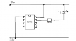
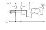
I am using two 08M2 chips and the circuits should be working.

I would be very thankful! ;)
 

westaust55

Moderator
Suggest that you post the schematic for the Tx and Rx parts so others know how you have the components wired (and whether correct or not)

Further if you post the code you have tried folks here may be able to quickly identify what changes are required rather than writing code from scratch.
 
Last edited:

Jamcof

New Member
I have tried those codes but they wont work.
But here are the schematics that I made with paint :D

Transmitter: transmitter.png

Receiver: receiver.png
 

erco

Senior Member
Easiest way to start is using a universal IR remote set up for Sony TV only. Make sure your IR receiver can read the remote codes, then make your transmitter.
 

hippy

Ex-Staff (retired)
Your LEDs in both circuits are the wrong way round. For the IR transmitter I can't recall whether cathode should be to 0V or output pin.
 

westaust55

Moderator
Transmitter circuit LED is okay.
The 5 V is at the bottom and 0 V at the top contrary to normal schematic drawing practice.
 

Jamcof

New Member
I just added the 10k resistors to both circuits and turned around transmitter's IR LED and put the LED's negative wire to output 0 and positive to 5V. And turned around the LED on receiver.

I tried this following codes for my circuits:
Transmitter's:
Code:
	for b0 = 1 to 10
	  irout B.1,1,3
	  pause 45
	next b0
And Receiver's:
Code:
main:	irin [1000,main],C.3,b0	
	if b0 = 3 then swon1	
	goto main

swon1: 
      low 0
	pause 1000
	high 0
	goto main
They won't work.

When I power up the receiver it turns on always the LED, but won't react in any way to transmitter.
 

hippy

Ex-Staff (retired)
Start with simpler code -

Code:
#Picaxe 08M2
Do
  IrOut C.1, 1, b0
  b0 = b0 + 1
  Pause 1000
Loop
Code:
#Picaxe 08M2
#Terminal 4800
Do
  IrIn C.3, b0
  SerTxd( "Received ", #b0, CR, LF ) 
Loop
 

Jamcof

New Member
So should the Terminal say "Received" when I turn on the transmitter? If so, then that won't happen. Maybe I have still something wrong with circuits.
 

hippy

Ex-Staff (retired)
Double check your wiring and you should be able to test the receiver by itself, using almost any remote, with the following. It should flash your LED and show an "Okay" message every time you press a remote button.

Code:
#picaxe 08M2
#Terminal 4800
Do
  Do : Loop Until pinC.3 = 0
  High C.1
  SerTxd( "Okay " )
  Pause 250 
  Low C.1
  Pause 500
Loop
Also; just noticed that your IR LED is connected to C.0 in your transmitter circuit diagram not C.1/B.1 as the program uses.
 

westaust55

Moderator
I just . . . turned around transmitter's IR LED
At post 8 I indicated the IR LED orientation was already correct.

One way to ascertain if the IR LED is working is to use the camera in your mobile phone.
With the phone camera on and looking at the LED you should see a white blob on your phone screen whereas human eyes cannot "see" IR light.
 

SAborn

Senior Member
What IR led do you have, as not all are in the right wave length to work with the IR receivers.

What IR receiver do you have as some require a small change to circuit wiring.

What distance are you testing the circuits over.

[/When I power up the receiver it turns on always the LED, but won't react in any way to transmitter.QUOTE]

That is because your indicator led is wired backwards, it needs to be between picaxe pin and ground, not picaxe pin and 5V, as you have it.
 
Last edited:

Jamcof

New Member
Double check your wiring and you should be able to test the receiver by itself, using almost any remote, with the following. It should flash your LED and show an "Okay" message every time you press a remote button.

Code:
#picaxe 08M2
#Terminal 4800
Do
  Do : Loop Until pinC.3 = 0
  High C.1
  SerTxd( "Okay " )
  Pause 250 
  Low C.1
  Pause 500
Loop
Also; just noticed that your IR LED is connected to C.0 in your transmitter circuit diagram not C.1/B.1 as the program uses.
Yes! It works with 3 different remotes. But won't react to my transmitter. I think I have wrong program on the transmitter.


What IR led do you have, as not all are in the right wave length to work with the IR receivers.

What IR receiver do you have as some require a small change to circuit wiring.

What distance are you testing the circuits over.

When I power up the receiver it turns on always the LED, but won't react in any way to transmitter.

That is because your indicator led is wired backwards, it needs to be between picaxe pin and ground, not picaxe pin and 5V, as you have it.
IR transmitter: LED021 5mm
and
IR receiver: LED020.
Testing at distance 10-20cm.
 
Top