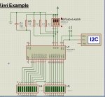
I have been only partially successful in simulating I2C communication with a MCP23016 16-bit I/O extender - and I am not sure where I am going wrong. My first attempt was a circuit that read the inputs off GP1 and then set the LED states on GP0, but I could not get the writes to GP0 to ever work.
I decided to back off and try a different circuit using the tried & proven code that BCJKiwi put up on this thread... again, only partially successful. The LEDs are initially set on GP0, but the states never change... and the GP1 states never get set nor change.
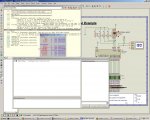
Insight into where I am fouling things up would be most appreciated... it almost seems like the CLK signal or something else is not working, so the chip never gets off the ground... although I believe it has been wired correctly per the datasheet. I have attached the BAS and DSN files below for the BCJKiwi code project.
I decided to back off and try a different circuit using the tried & proven code that BCJKiwi put up on this thread... again, only partially successful. The LEDs are initially set on GP0, but the states never change... and the GP1 states never get set nor change.
Insight into where I am fouling things up would be most appreciated... it almost seems like the CLK signal or something else is not working, so the chip never gets off the ground... although I believe it has been wired correctly per the datasheet. I have attached the BAS and DSN files below for the BCJKiwi code project.
Attachments
-
131.2 KB Views: 26
-
1.4 KB Views: 22