i2c NCP5623

George Sephton

Senior Member
Ive been looking around the internet for an i2c RGB Display Driver to enable me to run an RGB LED from one output and I found this: NCP5623 (http://www.onsemi.com/pub_link/Collateral/NCP5623-D.PDF) Has anyone used it before and did they come across any problems with it as I may order one soon and have a go. Ive looked through the datasheet and it seems like a really good driver, if anyone has used it how did they find the pwm output on it? Am I right in thinking I could make the LEDs fade with this?
George S.
 
it seems like a really good driver, if anyone has used it how did they find the pwm output on it? Am I right in thinking I could make the LEDs fade with this?
George S.
Haven't used this one, but looks like a nice part. Compared with the likes of the NXP and TI I2C led drivers, this one is a no fuss setup, and should get the job done easily. The 15 bits of color from your RGB led should be plenty.
 

George Sephton

Senior Member
Ive just found out that On Semiconductors are the only people that sell it and it costs about £10 just to order them so I won't bother, what were those other ones you mentioned because now I need to find an alternative, its a shame because that one looked really good.
 

George Sephton

Senior Member
The intention is to run an rgb led and an lcd screen from a picaxe 08m. Does anyone know of an i2c rgb driver on maxim, im looking around now to see if there's any I can sample, as the shipping charge from rapid is massive and maplin is very overpriced and doesn't do things like this.
 

eclectic

Moderator
The intention is to run an rgb led and an lcd screen from a picaxe 08m. Does anyone know of an i2c rgb driver on maxim, im looking around now to see if there's any I can sample, as the shipping charge from rapid is massive and maplin is very overpriced and doesn't do things like this.
George, a couple of points:

1. The controlling 08M cannot function in I2C mode. (X and X1 only)
See manual2 page 129

2. I didn't make myself clear in the above post.

A "control" 08M, which
a. Sends serout to a serial LCD and
b. sends a separate "serout" to the

B. second 08M, which functions as a simple RGB controller.

e

I hope that's clearer.
 

eclectic

Moderator
George.
Perhaps it might help, if you gave an overview of your project.
At the moment, there's a LCD and an RGB LED.

What's it all for?

e
 

hippy

Ex-Staff (retired)
@ George : You can bit-bang I2C from an 08M but it will use up a fair bit of the program code space and will also be considerably slower than on PICAXE's which have I2C command included. The 08M can only control other I2C devices not be an I2C device ( I2C Slave ).
 

George Sephton

Senior Member
Bit-banging, there's that word again. However I have just found a 2-wire serial port expander, this is good because it gives me 16 more I/O pins to use but is serial not i2c so it can be used with the 08M (shoudn't it?)

In answer to your response, ecletic, I'm building a "room" automation application. I'll have 2 LCD screens on each side of the room, one of which will have buttons on and will be handheld which will be charged and synced from a dock. The controller will control speakers, an ipod dock.... etc and the features include a "calming mood led thing" The main controller is being run from a 28X1 and the 08M is running the 2nd LCD which just copies what's on the first LCD screen, the 2 are linked wirelessly by infrared. That's the whole project in a nutshell. The main controller unit has a clock and alarm clock in it, and displays, humidity, light intensity and temperature inside and outside. I have most of the components and it doesn't actually cost too much.
 

eclectic

Moderator
Bit-banging, there's that word again. However I have just found a 2-wire serial port expander, this is good because it gives me 16 more I/O pins to use but is serial not i2c so it can be used with the 08M (shoudn't it?)

In answer to your response, ecletic, I'm building a "room" automation application. I'll have 2 LCD screens on each side of the room, one of which will have buttons on and will be handheld which will be charged and synced from a dock. The controller will control speakers, an ipod dock.... etc and the features include a "calming mood led thing" The main controller is being run from a 28X1 and the 08M is running the 2nd LCD which just copies what's on the first LCD screen, the 2 are linked wirelessly by infrared. That's the whole project in a nutshell. The main controller unit has a clock and alarm clock in it, and displays, humidity, light intensity and temperature inside and outside. I have most of the components and it doesn't actually cost too much.
Thank you for the reply.
The project sounds fascinating.
What are you using for the sensor modules?

e
 

eclectic

Moderator
Either an LM335Z or another one from maxim (yet to arrive) for temperature, a humidity sensor from rapid (http://www.rapidonline.com/Electronic-Components/Sensors/Humidity-Sensors/Humidity-sensor/80511) and a few LDRs. LDR and Humidity sensor both output an analogue signal in the same way.

Do you know if this (http://datasheets.maxim-ic.com/en/ds/MAX7312.pdf) would work with a PICAXE 08M
Just some comments on the sensors.

1. The LDR is very easy.
2. LM335? Plenty of info and comments on the Forum.

A minor ... but ....
the humidity sensor ....
Please view this thread

http://www.picaxeforum.co.uk/showthread.php?t=10131&highlight=humidity

Post #6 (AC required)
Post #11

It's getting a bit more complicated.

e
 

eclectic

Moderator
Plan B. Part 1.

Leave Humidity, for the moment.

Get Light and Temperature sorted.

(And, just my opinion ; DS18B20.)

e
 

papaof2

Senior Member
Since the humidity sensor only requires 1 volt and 200ua, with a frequency of 0.5 to 2000Hz, you could run PWM (or pulsout) on a pin, filter it a little to make a sinewave, and use a voltage divider to limit it to 1 volt.

One PICAXE pin, a few R and C components, and you have an AC supply for the humidity sensor.

Untested, but the idea is feasible.

John
 

George Sephton

Senior Member
TO-
ecletic: oh i will, i have to make an lcd screen work first which is proving to be difficult
John: please continue, I have never used the pwm command but have heard bits about it. I will have a look around the forum and see if anyone has a circuit for outputting an ac current.
Thanks.
 

eclectic

Moderator
TO-
ecletic: oh i will, i have to make an lcd screen work first which is proving to be difficult
John: please continue, I have never used the pwm command but have heard bits about it. I will have a look around the forum and see if anyone has a circuit for outputting an ac current.
Thanks.
George. LCD / working / difficult.

What LCD "screen" do you own, and,
what exactly IS working, at the moment?

e
 

George Sephton

Senior Member
The Hitachi one, i can't remember the name, but the one everyone (nearly) uses and unfortuately nothing (with this project....YET) It's just because I don't want to continue until I have my LCD screen working. Although i am currently setting one up with the 74LS164 at the moment.
 
Last edited:

eclectic

Moderator
The Hitachi one, i can't remember the name, but the one everyone (nearly) uses and unfortuately nothing (with this project....YET) It's just because I don't want to continue until I have my LCD screen working. Although i am currently setting one up with the 74LS164 at the moment.
OK. The easiest way is to start again.

It may sound boring,
but, what Picaxe and electronic kit do you own, now?

e
 

George Sephton

Senior Member
I had a 20M but broke it by moving it around too much, lesson learned. I have 2 08M and a 28X1. Kit? none, I have a lot of components and make my own PCBs.
 

westaust55

Moderator
Serial to Parallel chips

The Hitachi one, i can't remember the name, but the one everyone (nearly) uses and unfortuately nothing (with this project....YET) It's just because I don't want to continue until I have my LCD screen working. Although i am currently setting one up with the 74LS164 at the moment.
The 74LS164 is a TTL chip so there may be some compatibility issues between the CMOS PICAXE due to the differing voltage levels for high/1 and low/0 signals.

If so then the 74HC164 or 74HC595 which are CMOS devices may be a better choice.
 

George Sephton

Senior Member
If so then the 74HC164 or 74HC595 which are CMOS devices may be a better choice.
Is it worth me buying these: http://cgi.ebay.co.uk/74HC164-High-Speed-CMOS-ICs-10pk-25p-ea_W0QQitemZ220316874183QQcmdZViewItemQQptZLH_DefaultDomain_3?hash=item220316874183&_trksid=p3286.c0.m14&_trkparms=72%3A1301|66%3A2|65%3A12|39%3A1|240%3A1318

Those work in the same way? Same code and everything because Ive been follow hippy's 2-wire lcd interfacing. Just to say Ive tried both of hippys ways and the picaxe manuals way and had little or no real success.
 
Last edited:

westaust55

Moderator
TTL vs CMOS chip interfacing

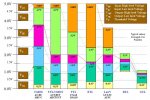
If you look at the attached diagram, CMOS to TTL is not a problem but TTL to CMOS (such as LCD driver chips) will be a problem. The 74HC range of chips overcomes this logic level voltage issue.

May be far from the end of the problems you are having but certainly worth selecting the right chips.
 

Attachments

westaust55

Moderator
LCD driver

I can only reiterate what eclectic has stated.
Please upload you schematic diagram and code.
There have been cases where members have adamantly stated “it is exactly as in the manual” but when they finally upload, problems can be seen. Code in manuals or elsewhere can/will be correct, but exactly what isyour code and circuit.
 

George Sephton

Senior Member
Well the schematic is exactly the same s the one on Hippy's page (and yes I know about the fact he's never tested it, but i have had a little bit of luck with it in the past, it always changes) and the code apparently is right but here it is anyway:
Code:
SYMBOL DAT = 1 ; Pin number of DAT line
SYMBOL CLK = 0 ; Pin number of CLK line

SYMBOL DAT_PIN = pin1 ; Pin number of DAT line

SYMBOL CLK_PULSE_LENGTH = 1 ; 10uS
SYMBOL E_PULSE_LENGTH = 1 ; 10uS

SYMBOL RSCMDmask = %00000000 ; Select Command register
SYMBOL RSDATmask = %00001000 ; Select Data register

SYMBOL counter = b2
SYMBOL get = b9
SYMBOL outbyte = b10
SYMBOL dataOut = b11
SYMBOL bitNumber = b12
SYMBOL rsbit = b13
SYMBOL CLR              = 2     ; Pin number of CLR line
SYMBOL CLR_PULSE_LENGTH = 1     ; 10uS


PowerOnReset:

GOSUB InitialiseLcd
Goto Main

END


Main:

outbyte = $80
gosub SendCmdByte

For counter = 0 to 4
lookup counter, ("Hello World"), outbyte
gosub SendDataByte
next counter

outbyte = "A"
gosub SendDataByte

goto main


InitialiseLcd:

FOR get = 0 TO 5
READ get,outbyte
GOSUB SendInitCmdByte
NEXT

' Nibble commands - To initialise 4-bit mode

EEPROM 0,( $33 ) ; %001?---- %001L---- Display Format
EEPROM 1,( $32 )

' Byte commands - To configure the LCD

EEPROM 2,( $28 ) ; %00101000 %001LNF00 Display Format
EEPROM 3,( $0C ) ; %00001100 %00001DCB Display On
EEPROM 4,( $06 ) ; %00000110 %000001IS Cursor Move

; L : 0 = 4-bit Mode 1 = 8-bit Mode
; N : 0 = 1 Line 1 = 2 Lines
; F : 0 = 5x7 Pixels 1 = N/A
; D : 0 = Display Off 1 = Display On
; C : 0 = Cursor Off 1 = Cursor On
; B : 0 = Cursor Steady 1 = Cursor Flash
; I : 0 = Dec Cursor 1 = Inc Cursor
; S : 0 = Cursor Move 1 = Display Shift

EEPROM 5,( $01 ) ; Clear Screen

RETURN

SendInitCmdByte:

PAUSE 15 ; Delay 15mS

SendCmdByte:

rsbit = RSCMDmask ; Send to Command register

SendDataByte:

dataOut = outbyte & %11110000 | rsbit
GOSUB TransferTo74LS164
dataOut = outbyte * %00010000 | rsbit
GOSUB TransferTo74LS164

rsbit = RSDATmask ; Send to Data register next

RETURN

TransferTo74LS164:

PULSOUT CLR,CLR_PULSE_LENGTH    ; Clear 74LS164

HIGH DAT                        ; Transfer data
PULSOUT CLK,CLK_PULSE_LENGTH
FOR bitNumber = 0 TO 6
DAT_PIN = dataOut / $80
PULSOUT CLK,CLK_PULSE_LENGTH
dataOut = dataOut * 2
NEXT

PULSOUT DAT,E_PULSE_LENGTH      ; Pulse E

RETURN                          ; Completed transfer
Like you said though it could be the ls164, by the way i ordered those hc164s it was a 10 pack so why not, dunno what else I could use them for though, ha!
 
Top