I keep trashing input trim potentiometers-thoughts

rogerm123

New Member
Would I need a back suppression diode for a trim potentiometer that I am using as an input voltage. After replacing twice, they perform on the first run but after power removed the 10k full scale reads approx. 5k full scale (the center pin now goes from 0-5k instead of 0-10k).
Set Up:
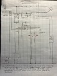
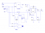
-small purchased power supply module to convert 115-5V. (it was advertised as "precision" so i assumed it had the capacitors and diodes to protect downstream)
-O8M2 chip has two outputs: 1-LED/resistor 2-relay control board with small relay to control 115V 80A relay
- I did tie down the serial input to ground through a resistor and added the capacitor across V+ and Vo
My thinking now is when I drop the switch on the 115V side the 115V coil in the 80A relay sends a spike out on that side and the power supply lets the spike follow through to the 5V side. question is why the potentiometers and not the 08M2??
 

papaof2

Senior Member
Did you test the pot out of circuit before installing it? There's always the possibility of something being mislabeled.
Was your after use test in or out of circuit? Even with the power supply disconnected, an in-circuit test will see 5k because the two 10K pots are in parallel.
 

erco

Senior Member
Both pots go from 0 to 5V but the wipers aren't in parallel.

Your drawing is a bit confusing but I don't see any reason you would be blowing pots. Double check your wiring. Obviously switching AC line voltage is risky. Perhaps your 5V supply is the problem, as it's connected right across your relay-switched AC motor. Try powering the Picaxe from an isolated 5V supply (batteries even) and see if it behaves differently.

Can you provide a photo of your setup & wiring?
 

Technoman

Senior Member
A blown pot having it's value exactly divided by two... is 5K the value measured when removed?
I would double check the wiring.
 

hippy

Ex-Staff (retired)
Very weird., and a rather unusual failure mode.

How have you determined that the pots are becoming 5K rather than 10K ? If measured in-circuit you could be getting misleading results.

The only thing I can think of is you are perhaps setting the ADC inputs as output pins which could cause issues, might even destroy the PICAXE if turned such that it creates a dead short to 0V or 5V.
 

rogerm123

New Member
Did you test the pot out of circuit before installing it? There's always the possibility of something being mislabeled.
Was your after use test in or out of circuit? Even with the power supply disconnected, an in-circuit test will see 5k because the two 10K pots are in parallel.
Test before install was 10k. I did not test after install before first run.
Note ,for testing, I am using the LED to basically blink the value read on the #1 and #2 inputs on initial power up. I divide it by 4 to shorten the process (0-255/4).
The first run the blinks were correct with the pot settings. the second run it was like they blinked the full 255/4 without changing the pot dial
 

rogerm123

New Member
Very weird., and a rather unusual failure mode.

How have you determined that the pots are becoming 5K rather than 10K ? If measured in-circuit you could be getting misleading results.

The only thing I can think of is you are perhaps setting the ADC inputs as output pins which could cause issues, might even destroy the PICAXE if turned such that it creates a dead short to 0V or 5V.
I am just using the command "readadc c.1,Vin" down in the program where Vin is my variable to store reading. How do you set up the pins?
 

hippy

Ex-Staff (retired)
You likely don't need to set up the pins for ADC. It is only if you use HIGH, LOW, TOGGLE, OUTPUT, REVERSE or 'dirsX=' on the same pin used for ADC which could cause a problem.
 

Jack Burns

New Member
If the “Current” switch is either ON or OFF as shown in the schematic, then pinC.3 will need a pulldown resistor to prevent the input from floating when the switch Opens. Without a resistor, pinC.3 could pick up random noise and that could cause your code to run erratically due to the floating input.

Please could you post your code so one of us can check it?
 

rogerm123

New Member
If the “Current” switch is either ON or OFF as shown in the schematic, then pinC.3 will need a pulldown resistor to prevent the input from floating when the switch Opens. Without a resistor, pinC.3 could pick up random noise and that could cause your code to run erratically due to the floating input.

Please could you post your code so one of us can check it?
Good observation, I should have thought about that-I will correct and let you know.
 

rogerm123

New Member
Attached is code.

Symbol coil = pinC.3 ; current flowing
Symbol relay=c.4 ; output to solid state relay
Symbol alarm=c.0 ;output to alarm when pump turned off
Symbol ctrSmall=b1 ; variable to count for 1 to durMin
Symbol ctrBig=b2 ; used to accumulate run times within an hour block
Symbol tInit=b3 ;start the hour timing duration
Symbol deltaT=b4 ; time count duration
;Symbol ctrBigVal=b5 ; accumulates small time durations within that hour count cycle
Symbol Vin=b6 ;analogue voltage input for determining user desired max small time to allow pump to be on
Symbol durMin=b7 ; converts input time voltage to minutes 1V=12min,5V=60min
Symbol Vin2=b8
symbol addDurMin=b9 ;additional min to add to durMin for accumulated max min/160min
symbol totAccumMinMax=b10;durMin + addDurMin


Start:
Low relay
Low alarm; not being used
tInit=Time
ctrBig=0
; FOR TESTING INPUT VALUES ''''''''''''''
readadc c.1,Vin
Vin=Vin/4
For ctrSmall=0 to Vin
High alarm
pause 500
Low alarm
pause 500
next

readadc c.2,Vin2

pause 5000
Vin2=Vin2/4
For ctrSmall = 0 to Vin2
High alarm
pause 500
Low alarm
pause 500
Next
;''''''''''''''''''''''''''''''''''''''
goto Runn

Runn:

deltaT=Time-tInit
if deltaT>7200 then ; reset accumulated time and timer each 2 hours-time is in seconds/ct
tInit=Time
ctrBig=0
endif
readadc c.1,Vin
durMin=Vin
if durMin=0 then
durMin=4;one minute minnimum-looping in 1/4min count below
endIf

readadc c.2,Vin2
addDurMin=Vin2

totAccumMinMax=durMin+addDurMin; looping below every 15sec so adc is in 0-255/0-5v/0-60min
if coil = 1 then ;current flow to pump
ctrSmall=0; reset for each pump start

for ctrSmall=0 to durMin
pause 15000;one quater minute 15sec

ctrBig=ctrBig+1
if ctrBig>totAccumMinMax then ; accumulated on time is greater than both time values added, in 120min block
goto TurnOff ;resets to 0 after 2hrs 120min
endif

if ctrSmall=durMin then ; if over set dur min continuous shut off
goto TurnOff
endif
if coil !=1 then
goto Runn
endif
next ctrSmall

endif
goto Runn


TurnOff:
;High alarm
High relay
goto TurnOff
 

Attachments

erco

Senior Member
Start with very short, simple code just to read & display the ADC measurements. After that works, add a little bit at a time and verify operation.
 

Goeytex

Senior Member
I see nothing in the schematic that would cause a potentiometer failure. However, do add the pull down resistor and you might want to add a 20uF electrolytic bulk capacitor somewhere on 5v line. Close to the Picaxe if possible.

My guess is either a wiring issue or not measuring the pots correctly. They must be "out-of-circuit to get a good resistance measurement.

Also check that the pots are wired up correctly. If ground or 5V is connected to wiper, then turning the pot all the way one direction will likely burn it out or damage the Picaxe.

Below is a schematic that I knocked up in LT Spice. It may be easier to read . It can be easily edited in MS Paint.

Goey

25633
 
Last edited:

Jack Burns

New Member
I'm not sure exactly how your code is meant to work, however, I notice that all your existing variables are byte variables which can only have a maximum value of 255. I believe in some cases you may need to store a value greater than 255, so a word variable would be required as that can have a maximum value of 65535.

Remember NOT to use word variables which overlap with the byte variables already in use., for example W8 uses both b16 and b17 which are both unused, so W8 is okay to use.

I believe these lines need changing, but there may be other byte variables that also need to be changed to word variables.
Code:
Symbol tInit=W8            ; was b3    ; start the hour timing duration
Symbol deltaT=W6           ; was b4    ; time count duration
symbol totAccumMinMax=W7   ; was b10   ; durMin + addDurMin
Also the "Time" variable can be set back to 0 (Time = 0) if that simplifies things for you.
 

rogerm123

New Member
I see nothing in the schematic that would cause a potentiometer failure. However, do add the pull down resistor and you might want to add a 20uF electrolytic bulk capacitor somewhere on 5v line. Close to the Picaxe if possible.

My guess is either a wiring issue or not measuring the pots correctly. They must be "out-of-circuit to get a good resistance measurement.

Also check that the pots are wired up correctly. If ground or 5V is connected to wiper, then turning the pot all the way one direction will likely burn it out or damage the Picaxe.

Below is a schematic that I knocked up in LT Spice. It may be easier to read . It can be easily edited in MS Paint.

Goey

View attachment 25633
Thanks, I will. Love the diagram.
 

rogerm123

New Member
I'm not sure exactly how your code is meant to work, however, I notice that all your existing variables are byte variables which can only have a maximum value of 255. I believe in some cases you may need to store a value greater than 255, so a word variable would be required as that can have a maximum value of 65535.

Remember NOT to use word variables which overlap with the byte variables already in use., for example W8 uses both b16 and b17 which are both unused, so W8 is okay to use.

I believe these lines need changing, but there may be other byte variables that also need to be changed to word variables.
Code:
Symbol tInit=W8            ; was b3    ; start the hour timing duration
Symbol deltaT=W6           ; was b4    ; time count duration
symbol totAccumMinMax=W7   ; was b10   ; durMin + addDurMin
Also the "Time" variable can be set back to 0 (Time = 0) if that simplifies things for you.
Thanks for pointing out the difference, and how to designate byte vs word variables. I was totally unaware.
 

rogerm123

New Member
To update: After a week with the chip laying on the bench I connected a 4.5v battery supply to the board vs 115/5V power supply, plugged the chip back in and turned it on. The pots were working as expected ie 30 count on one and 50 on the other. I thought for sure the draw down resistor was probably the solution on C.3 so I added it along with a 20microF capacitor across 5v lines. Turned the batteries back on and the count was back to full 255 count for each. Probably my inferior soldering/loose connection somewhere. I decided not to chase it and just program the values in code instead.

I have tested a resistive load on the main contacts and everything seems to be performing as expected. I will probably need the snubber and varistor installed before I hook to it's intended use to drop out an inductive motor.

I want to thank all those who responded with great help.
 

Goeytex

Senior Member
I would think that a common snubber of 100R/.1u across the relay contacts should be sufficient to prevent contact arcing at turn off.

A QuenchArch P/N 104M06QC100 Costs about $10 US.

Or make one (or 2) yourself with the properly rated components.

Goey
 
Last edited:
Top