i can't drive a servo with my 28x1 project board

Eindhar

New Member
hello to all, I hope to be posting in the right section.
I'm a totally newbie, thus this is my first project.
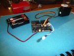
I'm trying to pilot a servo with my PICAXE 28X1 + ProjectBoard, but I'have several issues.
First of all, I soldered a new pin into Output 0's Ground, so now I'm connecting my servo with the yellow wire to the output, the red one on V+ and the black one on the G.
I'm supplying the system with 3 AA 1,5V stylo batteries, non rechargeable.
I replaced the Darlington chip with a 330R resistor and now I'm trying to pilot the servo but I have no results.
I tried to test the tension between output0 ground and V+ and it seems fine, so there's no line problems.
I used this code to run the servo

init: servo 0,75
main: servopos 0,75
pause 2000
servopos 0,150
pause 2000
servopos 0,255
pause 2000
goto main
then I went to PICAXE->Program... and it was successfully downloaded to the microcontroller, but then nothing happens.

To check the software i connected a LED on output4 and then I tried to flash it.
used simply the code

main: high 4
pause 1000
low 4
pause 1000
goto main
as you provided, and also here there's something strange. When i connected the blue LED to the powered project board, it turned on immediately. And it always stayed turned on, buth when it was given
command, it just become a bit brighter, and when
is given it simply dimes a bit.
The most curious thing is then, once i give to the controller the flashing program as provided, the LED flashes in the strange way I described, even if I connect it to any other output.

I'm guessing what am I doing wrong...

:(
 

g6ejd

Senior Member
Can you test your servo on a rc system? If not then try connecting the yellow wire to either gnd or +v and the servo should jitter, it may not depending on the quality of the servo. Try putting the yellow wire directly on the pin0.

Almost certainly you have a wiring problem.

Do you have a meter/DMV if so put it on dc volts and measure the voltage on pin0 it should be less than 4.5v and then switch it to ac volts and measure the volts on pin0 and there should be some ac if the servo command is working.
 

Eindhar

New Member
when i check for the firmware it says A.6
on another forum they told me that if so, the microcontroller might be slightly defective. can you confirm?

ANOTHER FUNNY THING:
I fed the program for moving the servo and nothing happens, but when i connect an unconnect the led on output7, the LED turns on, even if i did'n give the high 7 instruction, and the servo moves a bit to the right or the left in the very moment in which i extract the LED.

EDIT TWO: I definitely think it's defective now. Extracting the LED from pin-7 it magically started to execute the program normally, how it was supposed to be, after a reset.
but when i downloaded a different program in it, it stucked again.
 
Last edited:

westaust55

Moderator
when i check for the firmware it says A.6
on another forum they told me that if so, the microcontroller might be slightly defective. can you confirm?
which other forum are you talking about?
Version A.6 is the last Rev Ed produced which solved Servo related matters
V6 CORRECTED ISSUE WITH SERVO/SERVOPOS COMMAND WITH ODD NUMBERED WORD VARIABLES CAUSING JITTER
RECALIBRATED SERVO PULSE TIMING FOR MORE ACCURACY
DISABLED INTERRUPTS DURING 1-WIRE COMMUNICATION (READTEMP ETC.)


ANOTHER FUNNY THING:
I fed the program for moving the servo and nothing happens, but when i connect and disconnect the led on output7, the LED turns on, even if i didn't give the high 7 instruction, and the servo moves a bit to the right or the left in the very moment in which i extract the LED.

EDIT TWO: I definitely think it's defective now. Extracting the LED from pin-7 it magically started to execute the program normally, how it was supposed to be, after a reset.
but when i downloaded a different program in it, it stucked again.
Okay confused ???
Before you mentioned, and the photos show, an LED conenction to Output 4. But now we have mention of an LED on Output 7.

From your photo's I cannot immediately identify anything physically wrong with the conenctions to the AXE020 board.
 

westaust55

Moderator
Some further thoughts . . .

You are using 3 x 1.5V AA cells for the power.
Is this also for the SERVO motor?

The servo motor can pull a relative large current and the battery voltage may be dipping causing the PICAXE to reset.

I can think of no reason why the LED on Output 4 operates as it does. Since it is between the Vcc and PICAXE output, I would expect the LED to illuminate when LOW 4 was used and the LED turn off when HIGH 4 was used.
 

srnet

Senior Member
A servo such as shown, assuming its not faulty, might pull 100 - 200ma off load.

Mind you checking the power supply is what you think it should be has to be a very good idea.

I spent a good hour trobleshooting a new PCB yesterday, it would stop working properly when I illuminated all segments of a small 7 segment display. I assumed a PCB fault of course.

Turns out the supply volts was dipping because ................ I had the current limit set at around 40ma..........
 

Eindhar

New Member
First of all many thanks for your kind answers. I now answer to each one of you:

Westaust55
Ok, first I tried to connect the LED on pin-4 to try to flash it. And I discovered that I was not able to turn the LED off. With no program on the Microcontroller, with just the power supply of the three 1,5V AA batteries, if I connect a LED to any output pin (0 to 7) it turns on. When I give for example the program switching between low n and high n where n is the number of the pin to where I connected the LED, it doesn't turn off. It just dime a bit.
When i was trying to connect the LED in every pin, to check it out, I discovered that when i pulled the LED out from pin-7, the servo moved. I pressed reset on the PB and then the servo started to follow the program of centering. When I unplugged and plugged the batteries back in, the servo stood as still as dead.
Still I don't understend if it is correct that with just the battery pack and no program in the microcontroller, a LED connected to any output does turn on.
Second question, about the power supply. I pinned together V1 and V2 (it's not very visible in the picture), so yes, my battery pack is supplying the whole system.

srnet
how do i check if the servo is faulty?
in the fist page of the thread i reported the measurements of Voltages I did.
I don't think i have current limit set, by the way, the servo won't run the program, wether the LED is pinned in or not.
 

IronJungle

Senior Member
Eindhar:

You are in good hands with the advise you are getting.

One thing I noticed is that the 330R IC does not look like it is plugged in correctly in the photo (maybe it is). Can you double check to insure that you have the 330R IC legs seated into the correct holes in the socket?

Good luck.
 

BeanieBots

Moderator
The symtoms (esp. those of the LED) are indicative of a PICAXE with no 0v connection and being powered via the LED through an input pin.
As you are using a project board, the circuit is probably OK so I would suggest removing the chip and make sure one or more legs have not been folded under the chip.
 

Eindhar

New Member
hi to all, I know that I'm in the best hands, and I always thanks my friend here who constantly answer.
@IronJungle: the 330R is correct, as you may figure out, I'm following this roject to start http://letsmakerobots.com/start

@BeanieBots: duoble checked the pins, they are all fine and in place.
 

IronJungle

Senior Member
OK. I built the SHR awhile back and just dusted it off and looked at your pics. Your verification of the 330R is correct. Mine is offset in the socket as well.
I also verified on my SHR that you do have the servo plugged in with the correct polarity.

The SHR has been built a million times and, from my limited experience, the PICAXE is tough as nails so we should be able to sort this out.

This is what I would like to see:

- Pull the LED off the board. Leave the servo plugged in. Let's just focus on the servo.
- Double check (as mentioned before) that you do not have a leg bent in the IC sockets. DO THIS BY REMOVING ALL THE ICs and re-inserting them instead of just looking.
- I would like to see a pic of the backside of the PCB where you did the soldering. Especially the header pin area.
- Please verify you using a 28X1 PICAXE because this is what the project board expects to see.
- Verify good batteries and give us the voltage reading ACROSS THE PICAXE POWER AND GROUND PINS. Not at the battery this time, get the reading directly from the legs of the PICAXE. Assuming you have the PICAXE 28X1 (please verify) the "+" leg is #20 and the "-" leg is #19 and/or #8. Just for fun, let us know if you get the same reading when measuring the voltage on both "-" legs of the PICAXE 28X1.
- Download ONLY the code to move the servo. Let us know what happens and post the ENTIRE code. It should only be a few lines.

Please do all of the above no matter how stupid or obvious the seem. I thinking there is a bad or misconnection.

Now.... we wait....
 
Top