Hi Alan, Premelec, and Everyone,
I really appreciate the help!!!!!!!!!!!!
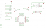
Thanks for the correction. I did put big question marks in red on the diagram because it didn't feel right, but I just am shooting in the dark. Is the following any good?
I don't know electrical theory. I have figured out certain things like transistors, MOSFETS, caps for filtering, diodes, and resistors, but that's about it.
(I am getting tendonitis with all this drawing with the mouse!)
")
In one application, it might be on-board, not just trackside. My fist step is to just get some numbers off of the motor. (The same motor is in most of these smaller items.) Here is what I am thinking: If I can get a reading under normal load then compare that to any increase in demand, I can make an assumption that the speed could be kicked up a couple steps, a crude idea, not precise, just yet. All I would need to know is if the number changes within a certain range.
Once I get some readings, I'll move on to the next step. Fortunately, I have a spare replacement motor (same motor in several things) I used when I first tried to get the PWM code working. So I will build another circuit on the readymade board with the HC-06 module, MOSFET, etc., the see if I can get the Bluetooth module to transmit back to the tablet. So far I only sent from the tablet to the board. Haven't done the SEROUT thing yet. As soon as I get some numbers off of the motor, I'll go from there. I just need a workable circuit for reading the ADC input.
Thanks again!
Take care, Joe.
P.S. I prefer not to have to stop the PWM to take a measurement, so that is why I am looking into BeanieBot's suggestion. J