how meany leds can a single channel power axe024
- Thread starter Jcdenton
- Start date
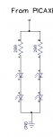
Each pin can only sink or source up to 20mA. Assuming you're using LEDs with a (generous) 3V forward voltage drop with those 200 ohm resistors, the total current for 4 will be 36mA, so you cannot control them all from one pin. The AXE024 has no high current drivers built in. You can use a transistor to drive them.Iv decided I'm going to take out the 330r and replace it with separate 220 resistors for each led.
What color LEDS are you using?
You could power 4 red LEDs at 10ma each with a series-parallel arrangement. Most of those crystal-clear high brightness LEDs will produce retina-searing light at 10ma (okay, slight overstatement, but they will be bright). Each series circuit would consist a 200 ohm resistor and 2 red LEDs in series, then you would parallel two of those directly across the PICAXE output and ground.
You could power 4 red LEDs at 10ma each with a series-parallel arrangement. Most of those crystal-clear high brightness LEDs will produce retina-searing light at 10ma (okay, slight overstatement, but they will be bright). Each series circuit would consist a 200 ohm resistor and 2 red LEDs in series, then you would parallel two of those directly across the PICAXE output and ground.
Attachments
-
 12.3 KB Views: 16
Many folks seem to think you need to drive LEDs at full power. The 330R resistor is a recommended minimum resistance to limit the Picaxe Pin current to a reasonable level. It is not the only resistance that can be used and is not really an optimal value. Most LEDs are quite happy at 3- 5 ma of current and give sufficient brightness at that current for use as indicators. I use 2K2 resistors much of the time, especially with Red LEDs that are nearly blinding when used with a 330R resistor. 4
The current drawn from the I/0 Pin is a function of the LED forward voltage and series resistance. Not all LEDs are the same and vary from MFG to MFG, batch to batch and from color to color. If in doubt, take current measurements with your meter.
With a 1K resistor on each LED, 4 LED's can be easily driven from a single I/O pin. If this is not bright enough, then bite the bullet and add a 20 cent 2N2222 transistor and run up to 10 LEDS or more given 10ma per LED. Don't be cheap, use a transistor if if needed.
rq3
Senior Member
Sometimes you won't need a resistor at all. The P channel (current sourcing) output impedance of a Picaaxe pin is about 80 ohms. Running a red led (e.g. 2.2 forward voltage) on a Picaxe running from a 3.3 volt supply gives 3.3-2.2/80=13.75 mA.
However, the N channel (current sinking) impedance is about 30 ohms, so at least an additional 25 ohms in series would be required for the above conditions.
However, the N channel (current sinking) impedance is about 30 ohms, so at least an additional 25 ohms in series would be required for the above conditions.
I don't think this is correct. According to Microchip, the output impedance of the average PIC chip (sink or source) is dependent on current, just as you would expect for a small MOSFET device. At the current you are talking about, the data sheet shows there would be about 10 ohms. 80 ohms into a short sounds about right, but that is a massive overload.Sometimes you won't need a resistor at all. The P channel (current sourcing) output impedance of a Picaaxe pin is about 80 ohms. Running a red led (e.g. 2.2 forward voltage) on a Picaxe running from a 3.3 volt supply gives 3.3-2.2/80=13.75 mA.
However, the N channel (current sinking) impedance is about 30 ohms, so at least an additional 25 ohms in series would be required for the above conditions.
rq3
Senior Member
It's certainly easy to measure. And I will admit that the values are somewhat variable from device to device. But in the case I quoted, they are tight enough to do without the resistor.I don't think this is correct. According to Microchip, the output impedance of the average PIC chip (sink or source) is dependent on current, just as you would expect for a small MOSFET device. At the current you are talking about, the data sheet shows there would be about 10 ohms. 80 ohms into a short sounds about right, but that is a massive overload.
Well,It's certainly easy to measure. And I will admit that the values are somewhat variable from device to device.
You could measure it for sure, and I seem to have a huge number of PICAXE chips, so I might do that at some later date. In the mean time though, Microchip have done that measurement out to a 25mA load.
Here is the graph for a PIC 16F7X, which I believe is a fairly typical item:
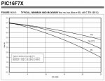
It clearly shows the output impedance increases (downward curve) as the current increases, and also shows that at about 14mA that impedance is around 10 ohms. I know you'd find variance between individual devices, but I wouldn't expect that value would ever be far outside the 9-11 ohm range.
I have to respectfully disagree.But in the case I quoted, they are tight enough to do without the resistor.
One last question please guys, I'm running on a 6v source so how does this look:
http://www.picaxe.com/docs/trt001.pdf
http://www.picaxe.com/docs/trt001.pdf
There is really no need to get an odd value 620 ohm resistor. Just use a standard 1K or really just about any value between 1K and 4K7. I actually prefer a value of 4K7 as this keeps the Picaxe I/0 current at a maximum of about 1ma, while limiting the total current through the transistor to about 180ma.
And as far as the resistor in series with the LED goes, the value will depend upon the brightness level you desire and/or what you need as far as power consumption goes. As has been stated before, A red LED will appear much brighter than a green LED given the same resistance value. 220 ohms might be a good starting point but may not be the final solution.
Also consider the nature of LED's. After about 50 percent of the rated current, doubling the current does not double the brightness. Most LED's are at peak efficiency ( Lumens per watt) somewhere between 50 and 70 percent of their maximum rating. Many times there is little perceived increase in brightness when driving an LED past 70 percent of its max. The extra current is simply wasted as heat.
Last edited:
I wouldn't say 620 ohm is all that odd a value, but your right. With this transistor you could easily get by with 4k7 or even more. I was just applying the over used 'Rule of Thumb' of 10:1. I am actually refreshed to see someone take the stance I usually take on this particular subject. In fact, with this transistor passing 100mA you'd likely be well into saturation with a 10K base resistor, especially if it was the 'C' version.There is really no need to get an odd value 620 ohm resistor. Just use a standard 1K or really just about any value between 1K and 4K7.
rq3
Senior Member
Billo, I think you're mis-reading the graph. While sourcing 14 mA, the high output pin can be anywhere between 4.2 volts (4.2/0.014=300 ohms) to 3.3 volts (3.3/.014=236 ohms).Well,
It clearly shows the output impedance increases (downward curve) as the current increases, and also shows that at about 14mA that impedance is around 10 ohms. I know you'd find variance between individual devices, but I wouldn't expect that value would ever be far outside the 9-11 ohm range.
I have to respectfully disagree.
To source 14 mA into a 10 ohm load, you'd only need a 0.14 volt output!
No, I don't think I am. The slope of that graph at any given point is the internal resistance of the PIC and the variance shown in the 3 lines is not only supposed to take in different parts, but more importantly (by far) a huge temperature range.Billo, I think you're mis-reading the graph.
Again, its the slope of the line that is the measure of the internal resistance or dV/dI not V/I, which would give you the load resistance. Also, you might observe that the slopes of those lines are not hugely different at a given current.While sourcing 14 mA, the high output pin can be anywhere between 4.2 volts (4.2/0.014=300 ohms) to 3.3 volts (3.3/.014=236 ohms).
Let me apologize as I may not have made myself clear. I am talking about the output or internal resistance of the device, not the load resistance.To source 14 mA into a 10 ohm load, you'd only need a 0.14 volt output!
Remember, I'm just eye-balling a graph here as I don't have an explicit mathematical expression to use. Now that I look a little closer it appears to me that the slope(s) at 14mA is(are) not far outside the range 9-12 ohms instead of 9-11. Please also be aware that that graph is meant to cover the temperature range from -40C to 115C. Such a temperature range would account for most of the variance. If we stick to something close to 25C, my money says that the resistance range between parts would be much, much tighter (maybe better than +.3 / - .2 ohm @ 14mA, just a guess though).
rq3
Senior Member
Billo, this is trivially easy to measure for a given condition. Don't do this for a 5 volt picaxe supply, as you will exceed the 25 mA Picaxe pin limit.No, I don't think I am. The slope of that graph at any given point is the internal resistance of the PIC and the variance shown in the 3 lines is not only supposed to take in different parts, but more importantly (by far) a huge temperature range.
1) Power the Picaxe from 3.3 volts.
2) Set a pin high
3) Apply a resistor decade box between the pin and ground
4) Dial down the resistance until the output pin is at 3.3/2=1.65 volts
5) The value of the decade box is now equal to the impedance of the output pin P channel mosfet
You can be very sure the decade box won't be anywhere near 10 ohms!
rq3
Senior Member
Let's forget the fact that the slope of a point is zero, and try this your way. Use the 25C "typical" plot. Between 20 and 15 mA (dI=0.005) there is a dV of, roughly eyeballing, 3.8-3.2=0.6 volts. dV/dI=0.6/0.005=120 ohms. Granted, it's not a linear function, but you're still off by an order of magnitude!Again, its the slope of the line that is the measure of the internal resistance or dV/dI not V/I, which would give you the load resistance. Also, you might observe that the slopes of those lines are not hugely different at a given current.
rq3, you might be making the mistake that I don't have a clue. Okay. No problem as I really don't have to convince you of anything.
Here is the plain facts of the matter, the slope of the load line is the internal resistance. End of story.
BTW, I know very well how to determine internal impedance/resistance, thanks.
BTW(II) Here is the load line for 3V.
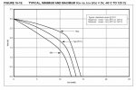
Again, just eyeballing it, it looks a though the slope at 1.5V is much, much more than 10. There appears to be a .4V change going from 1.2mA to 1.3mA, so the slope is nearly 400, indicating about 400 ohms of internal resistance at that point. One more point, I would NOT expect this same internal resistance at the 50% mark with Vdd = 5V.
Here is the plain facts of the matter, the slope of the load line is the internal resistance. End of story.
BTW, I know very well how to determine internal impedance/resistance, thanks.
BTW(II) Here is the load line for 3V.
Again, just eyeballing it, it looks a though the slope at 1.5V is much, much more than 10. There appears to be a .4V change going from 1.2mA to 1.3mA, so the slope is nearly 400, indicating about 400 ohms of internal resistance at that point. One more point, I would NOT expect this same internal resistance at the 50% mark with Vdd = 5V.
Last edited:
Okay, I give up. Just one last question, have you ever heard of calculus?Let's forget the fact that the slope of a point is zero
rq3
Senior Member
Yes, indeed. Most EE's have, and even taken (and perhaps taught) the subject. Billo, this isn't a pissing contest, and by resorting to personal inuendo it appears that you have seen the error of your ways, as you seem to have run out of "eyeballing" resolution.Okay, I give up. Just one last question, have you ever heard of calculus?
I have provided a very straightforward method of actually measuring the value in question. Also enlightening may be the Microchip 16F1829 datasheet, which is, I believe, the silicon upon which the Picaxe 20M2 is based (the device upon which I made my measurements). You may find the Voh and Vol vs pin current graphs enlightening once you understand how to read them.
I'll be glad to provide any assistance you may need.
@rq3.
No thanks. I have not seen the error in my ways and I am quite content with the knowledge that I have.
BTW, no innuendo at all. I was just asking because of your assertion. For someone to have be an EE and not know that a point on a continuous line has an associated slope is a little surprising though.
Also, please don't make presumptions on who I am or what my level of understanding is. Thanks. I leave you to your own.
rq3
Senior Member
The point itself has no slope. The line incorporating the point may or may not have a non-zero slope. I make no presumptions. I humbly ask you to demonstrate how, by eyeballing the graph provided, you arrived at a Picaxe MOSFET impedance of 10 ohms.@rq3.
No thanks. I have not seen the error in my ways and I am quite content with the knowledge that I have.
BTW, no innuendo at all. I was just asking because of your assertion. For someone to have be an EE and not know that a point on a continuous line has an associated slope is a little surprising though.
Also, please don't make presumptions on who I am or what my level of understanding is. Thanks. I leave you to your own.
In a continuous line, there is no point by "itself". Your statement is wrong.The point itself has no slope.
However, I already said I would do this experiment for real (and at 5V) when I have the time. I will do it properly and provide all with the data and the calculations. In the same experiment I will not only determine the full curve (from 5V to 0V), but will also reveal the maximum current a PICAXE can delver into a short circuit. In the mean time, since you won't believe me, you need to figure out what a load line like this is really telling you. The reason I state that is that mine will be no different, except that it will go beyond the 25mA that Microchip one does. If you don't do some study, you won't get any more out of it than you do out of the one they published. Others, I assume will. I will also plot internal resistance, but I'll be using that same reasoning I have done here. Which, BTW, is correct.
I estimated the slope of the load line. By looking at points on either side of, but close to, the point of interest Po = (Vo, Io) such that I had P1=(V1, I1) and P3=(V2, I2), where V2 < V0 < V1 and I2 > Io > I1. Now I estimate the slope (Ro) at Po as:I humbly ask you to demonstrate how, by eyeballing the graph provided, you arrived at a Picaxe MOSFET impedance of 10 ohms
Ro = (|V1-V2|)/(|I1-I2|)
Which, according to Ohms law, has the units of resistance.
For your further edification, I suggest you google "finding the internal resistance of a source signal" or something to that effect. But be careful. The method changes when the internal resistance is dynamic (as it is here) as opposed to static.
rq3
Senior Member
And this is different from my exercise (following your methodology) in post #19 how? Can you provide points from that graph, arbitrarily close together (your choice), so as to yield a result of anything like the 10 ohms you claim? Didn't think so.I estimated the slope of the load line. By looking at points on either side of, but close to, the point of interest Po = (Vo, Io) such that I had P1=(V1, I1) and P3=(V2, I2), where V2 < V0 < V1 and I2 > Io > I1. Now I estimate the slope (Ro) at Po as:
Ro = (|V1-V2|)/(|I1-I2|)
Which, according to Ohms law, has the units of resistance.
rq3
Senior Member
You're getting there. Now you're up to 400 ohms! What happened to 10 ohms? The original point here was that the Picaxe (Microchip) I/O pins have an internal resistance sufficiently high to negate the need for current limit resistors when driving LED's under some conditions. A safe working value is the P channel MOSFETS are about 80 ohms (may actually be as low as 60 if pushed towards the 25 mA maximum), and the N channel about 30 ohms.Again, just eyeballing it, it looks a though the slope at 1.5V is much, much more than 10. There appears to be a .4V change going from 1.2mA to 1.3mA, so the slope is nearly 400, indicating about 400 ohms of internal resistance at that point. One more point, I would NOT expect this same internal resistance at the 50% mark with Vdd = 5V.
rq3
Senior Member
Billo, you are a gentleman AND a scholar. Many thanks for making me think and recheck my results.Actually, I can't. I printed out the graph (5V) and did a graphical analysis and I was off by a order of magnitude. The internal resistance at 14mA is more like 100 ohms. Sorry about that.
Are you happy now?
Yes, I do agree, and I apologize for taking this thread to where it went. I made a silly assumption based on another device and then misread the graph with my assumption firmly in place.The original point here was that the Picaxe (Microchip) I/O pins have an internal resistance sufficiently high to negate the need for current limit resistors when driving LED's under some conditions.