Pongo
Senior Member
How do I figure out hspisetup for LTC1298? - Resolved
I've been bit banging LTC1298's but now I'm going to use one with a 20x2 so I thought I would use hspi. Seemed a good idea until I had to figure out the hspisetup command. Can someone point me to an idiot's guide to doing that? The LTC1298 datasheet can be found here.
I've been bit banging LTC1298's but now I'm going to use one with a 20x2 so I thought I would use hspi. Seemed a good idea until I had to figure out the hspisetup command. Can someone point me to an idiot's guide to doing that? The LTC1298 datasheet can be found here.
Last edited:
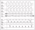
") I guess I'll just have to give that a try. I was hoping there was some hidden document somewhere that interprets this:
I guess I'll just have to give that a try. I was hoping there was some hidden document somewhere that interprets this: