Hot and Cold coolbox controller

davidwf

Senior Member
I developed this idea from CPEDW's project for a boat fridge controller, the aim being to control both the cooling and heating of my Peltier coolbox.
Being new to PIC's I am struggling with the heating bit so hopefully one of you will be able to help.
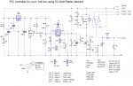
Outline description : as CPEDW I am checking the battery voltage first but only to see that it is above 11.9volts (PIC pin6)
Check to see if a switch on PIC pin 4 is operated (heating) or not (cooling)
If switch is closed operate a polarity changeover relay to reverse connections to the Peltier unit
Read the input from DS18B20 in PIC pin 3
Output PIC pin 7 to a high power Ultra FET transistor (=virtually zero on resistance)
The problem I am having is that when on heating, the relay releases when the hitemp value is reached
I am suspecting that I have made errors around line 50 as I can't get my head around the way it decodes the temperature values..I have read and re-read PICAXE manual 2 section 2 page 128 but I still cant grasp it.....how about an Excel sheet with the temp vs values on ????

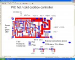
I have attached the listing together with a circuit diagram

thanks in anticipation
 

Attachments

Last edited:

davidwf

Senior Member
No, it is controlling the transistor Q2 which applies power to the Peltier via the polarity change relay.
Am I confusing things by calling it cool_off, perhaps Peltier _on(off) would be better ?

thanks for the prompt reply though
 

Attachments

Last edited:

BCJKiwi

Senior Member
Sorry, just had a quick look before and got mixed up.

The conditions are;
heat on and relay on
heat off and relay on

cool on and relay off
cool off and relay off

The code appears to achieve that.

Presumably this is a relatively slow changing temperature.

It may be that the tests should be changed so the line
IF actual_temp > hi_temp THEN heat_off ;Temp is above hi_temp point so peltier off
becomes
IF actual_temp >= hi_temp THEN heat_off ;Temp is above hi_temp point so peltier off.

At the present time, if the temp = hi_temp, then neither if temp tests are true and the code will move on to the next section which is Peltier_Off:
 

davidwf

Senior Member
Yes, the logic is correct
Yes it is a ralatively slow temp change
I will try your suggestion and report back - many thanks
Dave F
 

davidwf

Senior Member
I added the required = sign (and also one to the "cool" line) and it was no better.
The relay seemed to be operating briefly each time the peltier output line changed....I replaced the PIC and it didn't work at all - until I remembered to program it !!!!!
Now works as it should so it looks like a faulty PIC...not what I needed for a first project !
A few odds & ends to tidy up and I will publish the finished article

I am still confused with the "127" entry around line 40 though...could this be altered to similar entry as the heating request around line 48 ?...I don't understand how it handles the lower temperatures

Thanks to BCJKiwi for your help
 

BCJKiwi

Senior Member
Good to see it is working. Did you try reprogramming the original PICAXE?

I've not actually used a DS18B20.
However the key is in the readtemp command in Manual2;
"The temperature is read back in whole degree steps,
and the sensor operates from -55 to + 125 degrees celsius.
Note that bit 7 is 0 for positive temperature values and
1 for negative values (ie negative values will appear as 128 + numeric value)."

Thus the test < 127 is to check that the temp is a positive temperature.
 

BCJKiwi

Senior Member
As I don't have a DS18B20 I don't know exactly what is returned by the readtemp command as it moves through zero degC.

Perhaps you could set up sertxd to display the output as it moves through this temperature range. Then you would better understand what is happening and perhaps why the original program included that test. It was a program for cooling only so maybe the answer lies there.

Sorry but without practical experience on the the specific device, am unable to assist further.
 

davidwf

Senior Member
Did you try reprogramming the original PICAXE?
Yes, several times...it seemed to be working OK just that the outputs were not working as they should - or maybe the inputs, who knows....it's in the bin now, fortunately they are not too expensive.
 

davidwf

Senior Member
Have been de-bugging and changing the program....suddenly output pin 7 is high as soon as the power is applied (should wait 30 sec) and I cannot re-program the PIC (editor says hardware not found)
I have checked the program /run link on pin 7 and it is good.

Has the PIC blown up ???
any other ideas ?

Also, is it possible to add some hysterisis to the temperature set points - the temp is maintained to a commendably very tight window (typically less than 0.5 deg C) but I would like to increase it to, say 1 or 2 degrees.

Thanks
 

Attachments

Last edited:

BCJKiwi

Senior Member
Thanks for the temp to variable chart - will be useful. Trust this solved the queries regarding the pos/neg test.

Just completed a mini prog which included hysteresis (on readadc).

The trick was to introduce a 'third state'.
i.e. three states; < , between , and >.
e.g
If actual_temp > low_temp AND actual_temp < low_temp + 2 then goto top

i.e. just loop around without changing anything.

I see the code has been updated to include TOP_COOL and TOP_HEAT and the original TOP has been removed.
An alternative to this approach would be to return to the previous code and introduce the test code once associated with the pin3 test.
Save the last state of the heat/cool switch in a variable.
Compare the current switch position with the last switch position and the delay could be added before proceeding if required.
Simpler code, easier to follow.

untested suggestion;
Code:
symbol state = bx ' whatever is free - you decide on the variable to use
symbol hysteresis = 2 ' or whatever value delay you decide on
 
TOP:
pause 1 ' any delay you like - creates a delay between each program cycle.
If actual_temp > low_temp AND actual_temp < low_temp + hysteresis then goto top
 
READADC battery_monitor, battery_voltage
IF battery_voltage < battery_flat THEN PELTIER_OFF ;otherwise continue to next line
IF pin3 = 1 AND state = 1 THEN HEAT
IF pin3 = 0 AND state = 0 THEN COOL
IF pin3 = 1 AND state = 0 then
let state = 1    ' store new state
pause delay2
goto HEAT
Endif
IF pin3 = 0 and state = 1 then
let state = 0    ' store new state
pause delay2
goto COOL
Endif
or something similar.
 
Last edited:

davidwf

Senior Member
Oh dear...this is getting a bit above my head...I agree that your code is neater but remember I am brand new to PIC so I am taking the belt'n'braces approach.....untidy but easier (for me) to follow !

thanks for the advice, I WILL try to get my head around it !
 

Michael 2727

Senior Member
The simplest way to introduce hysterisis is to ad a delay to the
temperature sampling rate eg: 30 sec, 1 Min, 3 Min, 5 Mins.
 

eclectic

Moderator
David.
Your table of temperatures and values. (post #11)
Just looking at a few near zero.

Code:
 0	0
-1	255
-2	254
From Manual 2 page 128

"and 1 for negative values (ie negative values will appear as 128 + numeric value)."

"let b1 = b1 - 128 ‘ adjust neg value"

Shouldn't the table look something like
Code:
RTV	'C

128	 0
129	-1
130	-2
140 	-12
150     -22
and so on.

e
 

BCJKiwi

Senior Member
Sorry - did not intend to complicate things for you.

It's just that it was working before the changes.
Was trying to suggest a tidier way of implementing the changes you wanted while not introducing more complications to the logic.

Have reworked the last functioning program with the suggestions - trust this will be a bit easier to follow.

Code:
#picaxe 08M
; Coolbox Hot / Cold controller monitors supply battery voltage and temperature using DS18B20 
;  NOTE : To program PIC...power off, press F5 then power on immediately
; If battery voltage is above 11.9 V output depends on thermostat state if below 11.9V turn off altogether.
 SYMBOL battery_monitor  = 1 ;Connect battery via potential divider (33k, 15k + 10uF to Input 1 (Picaxe leg 6)).
 SYMBOL heat_out = 2  ;out to relay controlling heating via Output 2 (Picaxe leg 5)changes polarity to peltier 
 SYMBOL temp_monitor = 4  ;To DS18B20 via Input/Output 4 (Picaxe leg 3).
 SYMBOL peltier_out = 0  ;Out to transistor controlling peltier via output 0 (Picaxe leg 7 & prog / run selection link)
 
 SYMBOL battery_flat = 192 ;Corresponds to 11.9V (minimum voltage cutoff level)
      ;188=11.6V,190=11.75V,192=11.9V,194=12.0V,196=12.1V,198=12.25V.200 = 12.4V,
 
[I]SYMBOL Delay1 =30000 [/I]
[I]SYMBOL Delay2 =60000[/I]
[I]SYMBOL Hysteresis = 2  ;Hysteresis 2deg C[/I]
 
 SYMBOL low_temp = 6  ;(degC) temperature low_temp - actual temp is approx 1 deg above this setting (set=9, act=10.7)
 SYMBOL hi_temp = 64  ;(degC) temperature high temp - actual temp is about 1 deg above this setting
 SYMBOL battery_voltage = b0 ;Battery level reading
 SYMBOL actual_temp= b1  ;DS18B20 reading
[I]SYMBOL state = b3  ;Retain last heat/cool switch position[/I]
 READADC battery_monitor, battery_voltage
 READTEMP temp_monitor, actual_temp
 LOW peltier_out   ; petier off
 LOW heat_out   ; heat relay released
TOP:
PAUSE Delay1   ;Hysteresis to prevent power cycling of peltier element
 
 READADC battery_monitor, battery_voltage
 IF battery_voltage < battery_flat THEN PELTIER_OFF ;otherwise continue to next line
[I]IF pin3 = 1 AND state = 1 THEN HEAT[/I]
[I]IF pin3 = 0 AND state = 0 THEN COOL[/I]
[I]IF pin3 = 1 AND state = 0 then[/I]
[I]let state = 1    ' store new state[/I]
[I]pause delay2[/I]
[I]goto HEAT[/I]
[I]Endif[/I]
[I]IF pin3 = 0 and state = 1 then[/I]
[I]let state = 0    ' store new state[/I]
[I]pause delay2[/I]
[I]goto COOL[/I]
[I]Endif[/I]
 
COOL: 
 
 READTEMP temp_monitor, actual_temp
[I]If actual_temp > low_temp AND actual_temp < low_temp + hysteresis then goto top[/I]
 IF actual_temp > low_temp THEN PELTIER_ON  ;Temp is >low_temp so PELTIER_ON
 IF actual_temp <= low_temp THEN PELTIER_OFF ;Temp is at or below low_temp so PELTIER_OFF
 
HEAT:
 
 READTEMP temp_monitor, actual_temp
[I]If actual_temp > high_temp AND actual_temp < high_temp + hysteresis then goto top[/I]
 IF actual_temp < hi_temp THEN heat_on  ;Temp is below set temp point so peltier on
 IF actual_temp >=  hi_temp THEN heat_off ;Temp is at or above hi_temp so peltier off.
 
PELTIER_OFF:
 LOW peltier_out  ; Q2 off (-ve o/p off)
 LOW heat_out  ; heat relay remains released
 GOTO TOP
PELTIER_ON:
 HIGH peltier_out  ; activate cool o/p via Q2 on (PIC pin 7 via link)
 LOW heat_out  ; heat relay remains released
 GOTO TOP
heat_off:
 
 HIGH heat_out  ; keep heat relay operated
 LOW peltier_out  ; Q2 off, peltier off
 GOTO TOP
heat_on:
 
 HIGH heat_out  ; operate heat relay via Q1 (PIC pin 5)
 HIGH peltier_out  ; Q2 on, peltier on
 GOTO TOP
 

davidwf

Senior Member
David.
Your table of temperatures and values. (post #11)
Just looking at a few near zero.

Code:
 0	0
-1	255
-2	254
From Manual 2 page 128

"and 1 for negative values (ie negative values will appear as 128 + numeric value)."

"let b1 = b1 - 128 ‘ adjust neg value"

Shouldn't the table look something like
Code:
RTV	'C

128	 0
129	-1
130	-2
140 	-12
150     -22
and so on.

e
The short answer is that I don't know....it was devised following emails with CPEDW and his fridge cotroller, I THOUGHT it was correct but by all means feel free to change it as you see fit....at least it is a starting point !
 

davidwf

Senior Member
Sorry - did not intend to complicate things for you.

It's just that it was working before the changes.
Was trying to suggest a tidier way of implementing the changes you wanted while not introducing more complications to the logic.

Have reworked the last functioning program with the suggestions - trust this will be a bit easier to follow.
[/code]
WOW....MANY THANKS.....I will try it and let you know
Dave F
 

davidwf

Senior Member
Sorry - did not intend to complicate things for you.
[/code]
Hi again,
oh dear...looks like a slight error in lines 47 and 54 - see attached
Needless to say I can't see why it is failing....I DID however spot your deliberate mistake in labelling hi_temp as high_temp in line 54 but correcting that didn't get rid of the error....

Thanks
Dave F
 

Attachments

davidwf

Senior Member
BJCKiwi....I have tweaked my version again and although in "professional eyes" it may look messy, it does in fact seem to work quite well...apart from the fact that there is no hysteresis on the set temp.
Perhaps we could work with this version ?
Thanks
DF
 

Attachments

BCJKiwi

Senior Member
Sorry - I should have added - NOT TESTED.

Try this (at least it passes the syntax check);
Code:
#picaxe 08M
; Coolbox Hot / Cold controller monitors supply battery voltage and temperature using DS18B20 
;  NOTE : To program PIC...power off, press F5 then power on immediately
; If battery voltage is above 11.9 V output depends on thermostat state if below 11.9V turn off altogether.
 SYMBOL battery_monitor  = 1 ;Connect battery via potential divider (33k, 15k + 10uF to Input 1 (Picaxe leg 6)).
 SYMBOL heat_out = 2  ;out to relay controlling heating via Output 2 (Picaxe leg 5)changes polarity to peltier 
 SYMBOL temp_monitor = 4  ;To DS18B20 via Input/Output 4 (Picaxe leg 3).
 SYMBOL peltier_out = 0  ;Out to transistor controlling peltier via output 0 (Picaxe leg 7 & prog / run selection link)
 
 SYMBOL battery_flat = 192 ;Corresponds to 11.9V (minimum voltage cutoff level)
      ;188=11.6V,190=11.75V,192=11.9V,194=12.0V,196=12.1V,198=12.25V.200 = 12.4V,
 
SYMBOL Delay1 =30000 
SYMBOL Delay2 =60000
SYMBOL Hysteresis = 2  ;Hysteresis 2deg C
 
 SYMBOL low_temp = 6  ;(degC) temperature low_temp - actual temp is approx 1 deg above this setting (set=9, act=10.7)
 Symbol low_temp2 = low_temp + Hysteresis
 SYMBOL hi_temp = 64  ;(degC) temperature high temp - actual temp is about 1 deg above this setting
 Symbol hi_temp2 = hi_temp + Hysteresis
 SYMBOL battery_voltage = b0 ;Battery level reading
 SYMBOL actual_temp= b1  ;DS18B20 reading
SYMBOL state = b3  ;Retain last heat/cool switch position
 READADC battery_monitor, battery_voltage
 READTEMP temp_monitor, actual_temp
 LOW peltier_out   ; petier off
 LOW heat_out   ; heat relay released
TOP:
PAUSE Delay1   ;Hysteresis to prevent power cycling of peltier element
 
 READADC battery_monitor, battery_voltage
 IF battery_voltage < battery_flat THEN PELTIER_OFF ;otherwise continue to next line
IF pin3 = 1 AND state = 1 THEN HEAT
IF pin3 = 0 AND state = 0 THEN COOL
IF pin3 = 1 AND state = 0 then
let state = 1    ' store new state
pause delay2
goto HEAT
Endif
IF pin3 = 0 and state = 1 then
let state = 0    ' store new state
pause delay2
goto COOL
Endif
 
COOL: 
 
 READTEMP temp_monitor, actual_temp
If actual_temp > low_temp AND actual_temp < low_temp2 then goto top
 IF actual_temp > low_temp THEN PELTIER_ON  ;Temp is >low_temp so PELTIER_ON
 IF actual_temp <= low_temp THEN PELTIER_OFF ;Temp is at or below low_temp so PELTIER_OFF
 
HEAT:
 
 READTEMP temp_monitor, actual_temp
If actual_temp > hi_temp AND actual_temp < hi_temp2 then goto top
 IF actual_temp < hi_temp THEN heat_on  ;Temp is below set temp point so peltier on
 IF actual_temp >=  hi_temp THEN heat_off ;Temp is at or above hi_temp so peltier off.
 
PELTIER_OFF:
 LOW peltier_out  ; Q2 off (-ve o/p off)
 LOW heat_out  ; heat relay remains released
 GOTO TOP
PELTIER_ON:
 HIGH peltier_out  ; activate cool o/p via Q2 on (PIC pin 7 via link)
 LOW heat_out  ; heat relay remains released
 GOTO TOP
heat_off:
 
 HIGH heat_out  ; keep heat relay operated
 LOW peltier_out  ; Q2 off, peltier off
 GOTO TOP
heat_on:
 
 HIGH heat_out  ; operate heat relay via Q1 (PIC pin 5)
 HIGH peltier_out  ; Q2 on, peltier on
 GOTO TOP
 

davidwf

Senior Member
BCJKiwi.....many thanks for the update - I will try it tonight (is that tomorrow or yesterday for you - I never could remember !)
Thanks again
Dave F
 

davidwf

Senior Member
BCJKiwi,
Your modifications worked .... to a point.....you will see that I have re-labelled the variables with more meaningful names, tidied the layout and added more explanations.
I spotted the deliberate mistake (?) you left me to find in that the "hot" hysteresis actually needs to be "temp minus" rather than temp plus as it is on cool hyster.
I am still tweaking the hysterisis settings a bit and have added lines 33/34 & 41/42 to give better functioning of the unit and protection to the peltier if the mode switch is operated whilst switched on.
I have done away with the 30 second delay as, with hyster. it is not needed.
Thanks for your help - it was greatly appreciated and I am now starting to understand the way you approached it.
Perhaps you would kindly cast your eye over it again to see if any improvements can be made.
Dave F
 

Attachments

BCJKiwi

Senior Member
Looks good as far as I can see.

Was just trying to suggest alternative ways to do what you were wanting to achieve without actually doing all the work but its often easier to give the suggested code rather than trying to describe it.

So it was intended as a suggestion for you to complete which you have done.

Considering the comments above, I'm surprised there was only one 'deliberate' mistake!

Well done - there are so any ways to write code and it's always a learning process!
 

davidwf

Senior Member
We are the first - everyone else comes after
....hey mind your head on the doorframe....seriously though many thanks for your assistance with this.
Have done some final tweaking and attached the final program listing together with some graphs with the temp set at 7 and 62 deg C, I noticed that on the hot setting the temperature rises past the upper hysteresis value more than it falls below it and on the cooler temp setting it falls below the hyster value more than it rises above it...the only reason I could think of was possibly due to "heat soak" from the heatsink ???
I also noticed that the temperature differential was slightly greater at the hot setting than at the cold, any ideas on this - perhaps the DSB is not linear ?
I am not complaining, just curious as the circuit is more than adequate for its' intended use.
I am making some minor detail changes to the PCB layout and will upload it at a later date

Circuit diagram remains as in post #21
 

Attachments

Last edited:

BCJKiwi

Senior Member
"we are the first ... " - simple statement of fact resulting from the decision to place the date line right by New Zealand - i.e. as far as possible from Greenwich.

If I have understood the different behaviour description correctly, the greater over/undershoot would appear to occur when the Peltier/Coolbox is being powered whereas the lesser values occur when the Peltier/Coolbox is losing/gaining heat through conductance/radiation/whatever to the atmosphere. I would guess this would be a slower process thus the change is picked up closer to the set point.

This behaviour is likely to be less noticeable if the there is more mass inside the coolbox. It will also be affected by the location of the DS18B20 relative to mass being heated/cooled.
 

davidwf

Senior Member
The sensor is placed directly in the return airflow about 10mm above the heatsink, possibly the coldest spot ?
Watching the temp meter carefully, the cct. shuts off at the correct point and the temp then continues to rise just over 1 degree so I guess it must be the residual heat coming from the heatsink (heat soak)
 

davidwf

Senior Member
final enhancements

having used the unit for a while a couple of minor problems have become apparant....

the cable connecting it to the cigarette lighter drops about 0.8V when supplying load, this means the voltage detector needed tweaking down a bit as in line 8 of the attached revision.

Also when the unit cuts out due to low battery voltage, the voltage will obviously rise....which means it will start again....which means the voltage will drop....etc. etc. and it ends up rapidly cycling the peltier and the fan.
I added a revision to line 28 to include a delay in lines 80 - 84
It now pauses 60 sec between re-tries when the voltage gets low

....oh and don't forget to inhibit the ultra-sonic sensors of your car alarm if you leave it running whilst locked !!!
 

Attachments

BCJKiwi

Senior Member
You could replace the delay code with a different Voltage level test so It won't turn on again unless voltage is above a certain level.
 

davidwf

Senior Member
BJC...

I did consider that option - must be picking something up at last :rolleyes: ! - but found there is a lot of buggering about (sorry, experimenting :)) to get the correct voltage levels bearing in mind the voltage drop will change depending on the current being drawn.

Overall I think the time delay is the better option

Thanks
Dave F
 

cpedw

Senior Member
For my cool only box, I found heavy guage cable and no cig light er socket meant the voltage change was not too severe. I also included a capacitor on the potential divider to add a tiny bit of hysteresis.
Derek
 
Top