HopeRF issues

D n T

Senior Member
At the risk of the scorn of the forum I'm having issues with wireless and need a little assistance.
What I want to do:
Send 8 byte variable on a wireless link using the HopeRF modules.
These variables are attached to sensors and I have that end all sorted.
On the reciever end I would like to have the variables as they were .

I have been trying using the HopeRF modules(not the TTL units) and 20M chips on breadboard and keeping the enable high constantly.
The config has been grounded
I have built stans purring unit and it works 7 km LOS and across my desk very nicely thank you.
I tried to debug both the transmitter and the reciever and could not debug the reciever.

I went back to the 433mhz transmitter and reciever units we used pre HopeRF and I have been pushing a variable across the great divide no worries.
But when I went to use more than on variable the reciever seemed to pick up my pre amble rather than my variables.

Code:
`433mhz transmitter 08M

main:

b0 = 6
b1 = 12
b2 = 18
b3 = 24
b4 = 30
b5 = 36
b6 = 42
b7 = 48

serout 2,N1200,("UUUUUUUTW",b0,b1,b2,b3,b4,b5,b6,b7) 
high 1
pause 50
low 1
pause 100
goto main


`433mhz reciever 08M

symbol info = b0

main:
info =0
b1 = 0
b2 = 0
b3 = 0
b4 = 0
b5 = 0
b6 = 0
b7 = 0
serin 3, N1200, ("TW"),info,b1,b2,b3,b4,b5,b6,b7
debug info
pause 5
if info = 6 then correct
goto wrong

correct:
high 2
pause 20
low 2 
pause 20
goto main

wrong:
high 4
pause 20
low 4
pause 20
goto main
debug picks up b0 (info) as 6
but it picks up b1 - b7 as 85 ( which is U) this is my pre amble

If it was mechanical I could watch it and work it out, if it was a circuit issue I could work it out but not today.
I have looked at a lot of forum entrys and tried the african radio manufacturers method ( use some one elses and pull out parts, if it still works don't bother using it in the new design) I have even read the manual but I think I need a fresh approach again.
This is not for a school project I won't get extra credits and it is not due next week I just want to get this right to build my project.
HELP,
 

manuka

Senior Member
Happy to help- for general insights I suggest you visit my HopeRF resource page => http://www.picaxe.orconhosting.net.nz/hoperf.htm & also an older general PICAXE 433 RX/TX page => http://www.picaxe.orconhosting.net.nz/all3.jpg

Although your code could be tweaked & streamlined, the error seems just due to the sending line
serout 2,N1200,("UUUUUUUTW",b0,b1,b2,b3,b4,b5,b6,b7)
Fix this by inserting commas after each U & putting " " just around the TW preamble. Hence it should look -
serout 2,N1200,(U,U,U,U,U,U,U,"TW",b0,b1,b2,b3,b4,b5,b6,b7)
I usually use 85,85,85 strings instead of U,U,U as it happens. Thought- you may want to try the PULSIN trick I've shown at the resource site. Here's the code for it
Code:
'Simple HopeRF HM-TR TTL half duplex data exchange-Stan Feb.09
'PICAXE08M "Pin"1 -HopeRF TTL pin 6 (ENABLE),and status LED
'PICAXE08M "Pin"2 -HopeRF TTL pin 4 (DRX) data input from 08M
'PICAXE08M "Pin"4 -HopeRF TTL pin 2 (DTX) data output to 08M
'Uses PULSIN command as a handy timed out signal sensor.
'Consider PICAXE brown out detect (BOD) if v9.2 08M firmware
'Ref.schematic=> www.picaxe.orconhosting.net.nz/hopettlapp.gif
'Breadboard=> www.picaxe.orconhosting.net.nz/hopettlapp.jpg

hopettl:
high 1                   'bring HopeRF out of hiberation
serout 2,t2400,(85,85,85,85,"ttl",b0) 'tx beacon
pulsin 4,0,b1            'listen & briefly await any reply
if b1=0 then hopettl     'if nothing heard then resend beacon

serin 4,t2400,("ttl"),b0 'if signal heard then accept serial data 
low 1                    'enter low drain TTL sleep 
sleep 13                 'PICAXE low current SLEEP (~30 secs)
goto hopettl             'repeat routine

That 7km LOS link is pretty impressive, & would no doubt have even Mani in RSA swooning. (That's if he forgives your "african radio manufacturers method" comment- I thought it was only us Kiwi's who pushed for minimalist #8 wire approaches! ) Where was the link? If you're up to it, maybe even consider attempting the classic Freo- Rottnest WA wireless bridge. I've had emails from WiFi contacts who've patiently trialled this during the 18km ferry crossing. Stan
 
Last edited:

lbenson

Senior Member
Stan's suggestion doesn't pass a syntax check. But your code looks good to me. Can you confirm that the sender is not rebooting and so re-sending the preamble without having sent the original data (somehow?). Maybe put a "pause 1000" after main, and perhaps a "sertxd("About to send",cr,lf)".

Also consider womai's suggestion of putting a "pause 5" between the preamble and the data transmission.
 
Last edited:

MPep

Senior Member
DnT: you are inserting "info" in the received string, although it wasn't sent! Try removing that. Just a thought.
 

westaust55

Moderator
Also, over and above what Manuka identified . . . .

to take it another step (as previously discussed by womai) and also gives me greatest reliability (with Keymark 433MHz modules):

SEROUT 2, N1200, (U,U,U,U,U,U,U)
PAUSE 5 ; use a duration about equal to the duration for transmission of a byte but no more
SEROUT 2, N1200 ("TW",b0,b1,b2,b3,b4,b5,b6,b7)
 
Last edited:

hippy

Ex-Staff (retired)
As receivers like to see signals where there are equal numbers of one and zero bits it may be necessary to send dummy "U" bytes within the data for optimum reliability. Extending the preamble length, adding a short pause between preamble and qualifier can also help ...

SerOut ... ("UUUUUUUUUUUUUUUUUUUUUUUUUUUUUUUUUU")
Pause ...
SerOut ... ("TW",b0,b1,b2,b3,"U","U",b4,b5,b6,b7)

SerIn ... ("TW"),b0,b1,b2,b3,dummy,dummy,b4,b5,b6,b7

Also, check baud rate polarity (Nxxxx or Txxxx ) as this may differ between RF modules.
 

moxhamj

New Member
Re the Hope modules it is a pity you can't get them working. Don't give up on them yet!

1) You don't need UUUUUU for the Hope modules.
2) Hope modules won't work if they are too close (? 1metre). Ditto raw RF modules.
3) Does it send all 8 bytes b0 to b7 when connected with a wire?
4) For debugging, maybe just send b0. Then try it with just b0 and b1 etc.
5) Do you have a scope? It can be very useful to put the transmitter into just sending "U" and scope the output of the receiver RF modules. I found all sorts of waveform changes due to an arm being too near the board, due to the boards being too close etc.

Given the code looks ok, I'd be suspicious of RF interference, boards too close, hash from a PC and things like that.
 

D n T

Senior Member
Thanks

changed code to :
serout 2,N1200,("TW",b0,b1,b2,b3,b4,b5,b6,b7)
and
serin 3, N1200, ("TW"),info,b1,b2,b3,b4,b5,b6,b7
and the first three variables are stable
I tried the comms between the Us but they came up as variables,
b0 = U
b1 =,
b2 = U
b3 = ,
Tried inverted commas around only the TW and the syntax didn't like it.
Manuka, I will try out you code for the hope modules.
I'm a happier camper.
I still need to find out more so I will need more help
Thank you.
by the way, apparently the modules need 4.5 volts minimum, I will be using a regulated power supply now
 
Last edited:

manuka

Senior Member
HopeRF transceivers use superior FSK, rather than the on-off ASK of cheap units, but a bit of a UUU "wake up" call never hurts I've found. I'd been exploring preamble use for PULSIN work anyway.

Yes- they need at least 4.5V, but for initial walkabout testing consider 3 x fresh AA alkalines (which typically give 4.8V under light load), or 4 x 1.2V NiCds. Thought: Use SERTXD (rather than DEBUG) perhaps to streamline your tweaking too. Stan
 
Last edited:

moxhamj

New Member
The regulated power supply might be quite critical. I've always done RF work with regulated battery supplies ie 7 nimh/nicads and a LP2950 5V reg. There are too many variables if you have an unregulated supply, especially one where the volts collapse as the device comes on. I would be suspicious this is what is happening here as you are getting the first few bytes through but not the rest.
 

Grant Fleming

Senior Member
by the way, apparently the modules need 4.5 volts minimum, I will be using a regulated power supply now
Yes DnT, I can tell you that is the case from experience!
Originally I was using a battery pack but with all the experimenting in setting up they got a little low on voltage (without me realising), enough to power the PICAXE's but not enough for the Hope modules.
I also use a regulated power supply now for the HopeRF modules.
 

D n T

Senior Member
Feeling debuggered stil not debugging

Regulated power supply
Using 2 x 20M chips
simplifed code
marker LED to let me know what happening
watching the hope modules and they are transmitting and recieving but the 20M reciever chip is not picking any thing up,
the module is outputting to the 20M but the 20M is not registering
Program:
`HOPE RF MODULES 20M transmitter

b0= "H"
b1= "E"
b2= "L"
b3= "L"
b4= "O"

main:

high 0 ` enable
pause 10
serout 7, N1200,("UUU")
pause 5
serout 7, N1200,(b1,b2,b3,b4)
high 1
pause 50
low 1
low 0
debug start

goto main


`HOPE RF MODULES 20M reciever

main:
high 2
high 0 `enable
serin 1,N1200,("UUU"),b1,b2,b3,b4,b5,b6,b7,b8

pause 50
low 2
low 0
debug

goto main

With out the UUU qualifiers it will debug but the readings are 248,128,248,128,248,248,128,248.
Interference or some thing?
Do the Zigbee modules take care of the "hand shaking" ( is that what its called) so I can just funnel variablles into it and have tham come out the other end the same? I need this link for two projects, on a remote mobile sensor array and another a remote control and it would be nice if it was reliable, I'm running out of hair

I would like to know what is going on at the other end, its like driving down the road with earmuffs and the windows painted in, although I have not done that yet.

P.S. Its ANZAC day today
 
Last edited:

manuka

Senior Member
I teasingly suspected your bug was due to saying "HELLO" instead of "GIDDAY MATE"! Before further probing, can you please inform about your environment & likely interference sources. ANZAC dawn parade here in NZ too- well make that "dawn +" in my case - so more later. ANZAC day historically means ex. pats "up top" in Britain shiveringly drag out the BBQ.

PS- several WA regular posters near you have extensive PICAXE + 433 MHz experiences. Try WESTAUST55 ?
 
Last edited:

KIGX

Member
DnT:

Don't know what the specific problem is but in your last set of code you are trying to SERIN more variables than you SEROUT so the serin is going to hang.

I usually serout more variables than I serin - add dummies (UUUUs) to the end of the serout but don't bother trapping them with the serin. That way the serin variables always (mostly) get filled with something and the serin won't hang when things go awry from interference etc.

Edit: Looking at the first code you posted, you have debug right after the serin. I have seen debug mess things up and maybe this is one of those cases. Try to Sertxd the variables instead of debugging.
 
Last edited:

D n T

Senior Member
Surroundings etc

The two modules are talking to eachother( they are transmitting and recieving at the right times)
The 20M does not seem to want to debug when the qualifier is present
I have tried the modules on my desk with my wireless internet, wirleless network card, neon desk lamp and mobile phone all within three feet. The 20M is not reading.
I tried transmitter out the front of the house and the reciever out the back same result, by the way, no powerlines, underground power here.
The modules seem to be functioning perfectly.
I think I might have to try wired serial... in a minute.. or an hour or so, my delicate breadboarding touch semms to have disappeared, perhaps some gardening will help and a coke ( the coca cola kind of coke with the registered name and all the details)

See you all in a couple of hours.
 

moxhamj

New Member
Re "Do the Zigbee modules take care of the "hand shaking" ( is that what its called) so I can just funnel variablles into it and have tham come out the other end the same?"

Yes, and the Hope ones do too. I've sent text files of 100,000 bytes using these modules and they do work well once you have them set up right.

You don't need qualifiers or Us with the Hope modules, though it doesn't matter if you put them in.

Try just serout 7, N1200,("A") and no receive picaxe for the moment.

feed that into a hope module. You should see the (red?) led flash on that module, and you should see the (?green) led flash on the receive module.

If that works, then data got through. But if it didn't, I'd be suspicious that the hope modules have been programmed with different baud rates, or that they are too close (try >1m).

There are quite a number of serious bugs in the code in post #14 which we will get to, but the first step is to get a hope module to receive data from another one.
 
Last edited:

D n T

Senior Member
red, green flashes

When I transmit "A" at N1200 ( they are both programmed at 1200)
the transmitting module flashes red
the reciever flashes green at "the same time"
tested them at 6 inches and 60 feet same result

check...
standing by...
 
Last edited:

manuka

Senior Member
Well it is a tad fuzzy IMHO (& I speaka da Anzac lingo), so perhaps it's time the original poster first got down to 433 Tx/Rx basics. DnT - have you checked HopeRF resources etc at => http://picaxe.orconhosting.net.nz/hoperf.htm ? Have you grabbed a RF scanner & tested for local channel interference ? Have you had success with simpler 433 Tx/Rx ? Can you PLEASE shoot us a picture, schematic & code of your layout. Stan
 

westaust55

Moderator
DTN,
notice in a post of yesterday that you are using the "UUU' seemingly both as a preamble and qualifier.

Unfortunately in terms of helping you I have not read up on the HOPERF 433MHZ modules - they are a future project/experiment as I have been using the Keymark modules to date.

If receiving commas ( , ) seems to be a timing/synchronising issue.

While noting others suggest the "UUU" type preamble is not essential with the HOPERF modules, assuming you retain it (it should give the receiving PICAXE a better chance to synchronise) , then use a different qualifier (eg ABC) to flag the start of real data. See code below:

Code:
`HOPE RF MODULES 20M transmitter

b0= "H"
b1= "E"
b2= "L"
b3= "L"
b4= "O"

main:

high 0 ` enable
pause 10
serout 7, N1200,("[COLOR="Red"]UUUUUU[/COLOR]") ; add few few more
pause 5
serout 7, N1200,("[COLOR="Red"]ABC[/COLOR]",b1,b2,b3,b4)
high 1
pause 50
low 1
low 0
debug start

goto main


`HOPE RF MODULES 20M reciever

main:
high 2
high 0 `enable
serin 1,N1200,("[COLOR="Red"]ABC[/COLOR]"),b1,b2,b3,b4

pause 50
low 2
low 0
debug

goto main
 
Last edited:

moxhamj

New Member
Re "When I transmit "A" at N1200 ( they are both programmed at 1200)
the transmitting module flashes red
the reciever flashes green at "the same time"
tested them at 6 inches and 60 feet same result"

Cool. You almost have it working. The "A" will be there at the receiver. You just have to get it out. Westaust has already pointed out the changes needed to the code.You can simplify it even further on the Tx:

serout 7, N1200,("UUUUUU") ; add few few more
pause 5
serout 7, N1200,("ABC"),b1,b2,b3,b4

can all be in one line
serout 7, N1200,("UUUUUUABC"),b1,b2,b3,b4


On the Rx to quote the code in post #22 verbatim
serin 1,N1200,("ABC"),b1,b2,b3,b4)

Just leave out that last )
serin 1,N1200,("ABC"),b1,b2,b3,b4

Now it should work. It will hang in serin till it gets an ABC. Then it will read the next 4 bytes.

Addit: I just noticed two things in your post. First, you gave some readings "With out the UUU qualifiers it will debug but the readings are 248,128,248,128,248,248,128,248."

Second, in your very first post you said these are not TTL modules.

Those numbers look a bit like inverted numbers, ie all 128 to 255. Most ascii numbers are 32 to 127. That would happen if you have RS232 modules which invert the data going in. You will still get data out, but it will be inverted. Can we please have a bit more info - a schematic, a photo (eg like the ones Manuka has of his modules on a protoboard - they are so clear you don't even need a schematic). If you do have RS232 modules, then you might need a max232 at either end. Do you have the specs on the module, or can you take a photo so we can see if the max232 chip is on the module?
 
Last edited:

westaust55

Moderator
Thanks Dr A,
though I had removed that trailing bracket ")" :eek:
Fixed in case others copy my code without reading your post as well.

EDIT: Ah spotted my error, I removed the wrong bracket. :eek:
Note for SEROUT, even the data in enclosed in the brackets
serout 7, N1200,("UUUUUUABC", b1,b2,b3,b4)
whereas for SERIN only the qualifier part is enclosed within the backects
serin 1, N1200,("ABC"), b1,b2,b3,b4


the intent of the pause 5 between the 2 SEROUT commands is to nominally get the receiver and PICAXE synched with the 10101010. . . pattern from the "U's" as the preamble and start afresh with the data transmission just in case the receiver is out slightly (ie by say 1 bit) in terms of the preamble data which could lead to receiving PICAXE "Seeing" incorrect bytes.

Womai first described this and until I started doing the same, I was getting occassions (using the keymark modules) with packets of data seeing the "U's" as data from time to time. Since adding that small pause 5 to 7ms (use ~10 to 15ms at 600 baud) I have experienced no problems and received data has always been 100% valid. :)
 
Last edited:

hippy

Ex-Staff (retired)
For 433MHz interfacing the moral seems to be -

* Get the baud rate and polarity right for the modules being used

* Use receiving code along the lines of -

Do
SerIn rxPin, baud, ("XY"), b0
Loop

* Use transmitting code along the lines of -

b0 = "Z"
Do
SerOut txPin, baud, ("UUUUUUUUUUUUUUUUUUUUU")
Pause time
SerOut txPin, baud, ("XY", b0 )
Pause 1000
Loop

Then it's really a matter of finding an appropriate time and how many U's need to be sent, finally reducing the transmitting loop time, sending and receiving the actual data desired and altering qualifiers as necessary.

The U's are there as a pre-amble to kick the RF receiver into a state it is ready for receiving subsequent data without corruption. Sending too many shouldn't be a problem.

The PAUSE between the U's and the qualifier is there because the receiver's SERIN may have started to synchronise to one of the U's received part way through and without it the first part of the qualifier may be taken as the last part of a previous byte so SERIN never sees valid qualifiers. The PAUSE ensures the U's have all gone by and, regardless of what SERIN has seen, it will be ready and waiting for the start of the qualifier when those are sent. The length of PAUSE should be at least the length of time it takes to send a single byte at the specified baud rate.

The qualifiers are used so SERIN doesn't accept any data from the RF receiver until it is in a steady and stable state for receiving, ignoring any corrupt data which may arrive when it isn't.

The process is akin to ringing a bell in a crowded room before a speaker says what they have to. The bell silences the chatter, the pause lets the ringing in one's ears fade away. After that whatever is said can be heard clearly, the qualifier letting you decide if it's someone you want to hear from or not.
 

D n T

Senior Member
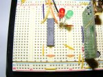
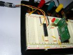
Posting pictures of units

The hope modules are not ttl, they have the rs232 chip hence possible inverted information. (how do I fix that?).
The download resistors are soldered to the jack, not mounted on the board.
note the jump wire to the enable leg is obscured by the module.

Both the transmitter and the reciever are the same design

I have learned much from this little discussion and I thank you for your patience
 

Attachments

SilentScreamer

Senior Member
The hope modules are not ttl, they have the rs232 chip hence possible inverted information. (how do I fix that?).
I don't know much about serial comms however I think you can just change N1200 to T1200 (or vice versa). The "T" and "N" stand for True and INverted.
 

D n T

Senior Member
Inverted information and that other photo of the unit

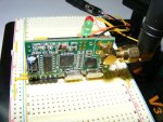
Here is the missing snap of the unit itself.
I thought that if the information went in and was inverted by the RS232 module on the transmitter, then it would be inverted again ( reverted or uninverted) in the RS232 module in the reciever.

Still learning, waiting for the next installment
 

Attachments

hippy

Ex-Staff (retired)
The hope modules are not ttl, they have the rs232 chip hence possible inverted information. (how do I fix that?).
If they work 'as is' when connected to a PC's serial port then you will want to use an N baud rate on the PICAXE, plus 20K serial Resistor for SERIN.

The way I remember it is "N for Normal ( PC use )", "T for The Other One".
 

moxhamj

New Member
Ah, RS232 ones? Well, in theory if you put N data in you should get N data out. The problem is that a Low (0V) is not a valid RS232 level. RS232 uses any voltage >3V as a signal pulse and any voltage <minus3V as the resting value. So the usual state of affairs is that RS232 rests at something like minus 12V, and a signal goes through and the pulses go to +12V. A max 232 changes minus 12V to +5V, and plus12V to 0V. Confused yet?

So, at the receive end, you might get away with using the 22k and 10k circuit on a picaxe input pin.

On the transmit side though, you are feeding 0V and 5V into an RS232 input that is expecting minus 12V and plus 12V. So when you feed 0V in, it is unclear to RS232 whether this is a high or a low.

The RS232 chips inside a PC do accept TTL logic levels. Ie they accept 5V as if it was +12V (which is valid because any voltage 3V is ok), and they accept 0V as if it was anything less than minus 3V. This is how the picaxe is able to talk back to a PC without a max232. But I'm not 100% sure of what a max232 (ie the one on the hope module) will do with a zero volt input. Will it interpret it like a PC?

Maybe it does, because you say you are getting data going through.

Do you have a couple of max232 chips lying around? The formal way to do this is to use max232 chips at both ends and then you are dealing with 5V and 0V. Or use TTL versions of the hope module. A couple of max232s will be cheaper though.

Which bits are working now and which are not? Do you have any data going through and is it correct or scrambled?
 

lbenson

Senior Member
Or, for RS232 modules, put a PC at the sender end and see what you get on the receiver when you type into hyperterminal or Putty. Or put the PC on both ends with the sender and receiver in the middle. Test first with a loop-back (which can be as simple as an allegater clip shorting pins 2 and 3 on the DB9 plug). Then, with common grounds, connect pin 3 to the Hope sender and pin 2 to the Hope receiver. What you type should come back and echo on the terminal. (This is assuming a real serial port on the PC end, or a USB-to-serial link which presents real RS232 levels, not +5V and 0V.)

When a loop from and to the PC works, put your receiver in place and confirm that it receives what you are sending from the PC. When that works, put your sender in and get that working. If you have trouble with the sender, hook it up to the PC and see what you are receiving.
 
Last edited:

MPep

Senior Member
Does it all work ok when the RF modules are out of the way, and SerIn is directly connected to SerOut? Start with that. If it all works okay, then add the RF modules.
 

D n T

Senior Member
Is it worth getting the TTL units??

Hippy,Stan, Dr etc is it worth me getting a pair of TTL modules to get this right without the RS232 issues?
 

manuka

Senior Member
DnT: I'd initially recommended RS232 versions for (gulp in your case) their ease of use! The barebones TTLs are however now my PICAXE favourites,largely due to their snoozing at very low currents. However - gasp- their setup is more complicated, probably requiring a MAX232. See a full account ( & workarounds etc ) in the April 2009 "Silicon Chip".

HAVE YOU TRIED CODE TWEAKS MENTIONED ???? Stan.
 

hippy

Ex-Staff (retired)
Hippy,Stan, Dr etc is it worth me getting a pair of TTL modules to get this right without the RS232 issues?
I'd have said, not immediately. As lbenson suggests, get these modules working as PC controlled directly from COM ports ( not USB-to-serial which could have 5V issues as well ). Once PC-to-PC is working you can try PICAXE-to-PC and PC-to-PICAXE, that will let you know what does work and what doesn't, and identify what needs to be fixed.

But, on the other hand, with all this kerfuffle and still probably having to hack some interface circuitry it probably is easier to buy TTL modules and use those. As Manuka asks; have you done what is suggested, are you sure it's a voltage level issue ? It would be a good idea to post your latest transmitter and receiver code.

It has to be said, despite noted limitations of range and signal penetration, XBee modules after simple configuration are plug-and-go and they cut out the necessity of protocol handling, tinkering and fine-tuning. A week on, numerous posts later, and still not working suggests that RF linking is not something which is easily tackled when things don't immediately work as expected and little experience of getting such things to work. It seems to rapidly turn into an internet game of twenty questions on "what's in the bin-bag I'm kicking ?" with the person answering the question not knowing what's inside to start with. No offence intended and PICAXE perhaps has to shoulder some of the blame, often making things so easy that it seems anything is possible and equally easy. A bit like suggesting building a house is no more complicated than throwing up some walls and putting a roof on top, building a kit car is just a matter of putting the pieces together.

I must admit though that I am somewhat confused. Going back to post #1 ...

"I have been trying using the HopeRF modules... I have built stans purring unit and it works 7 km LOS and across my desk very nicely thank you ... I went back to the 433mhz transmitter and reciever units we used pre HopeRF"

Are we still talking about using HopeRF modules or something else ?

If the HopeRF modules work in whatever Stan's unit is then they should work on breadboard. If those are TTL rather than RS232 modules, I'd suggest swapping the ones out of Stan's unit and seeing if your setup works with them.

Also, "I have been pushing a variable across the great divide no worries" - so what was working, what's changed ? Does that still work ? If the modules worked then they should work now, so no need to buy new ones.

I think it's time for a recap. Details of what we have, what does and doesn't work, along with some circuit diagrams and source code. Get everyone on 'the same page', clear about what we have, maybe even start a new thread to move on from there.
 
Last edited:

moxhamj

New Member
Yea, what he said...

Don't buy anything more just yet. You have enough parts to do some more experiments that will narrow down the problem. Can you work through the things from post 32 to 36 and let us know?
 

D n T

Senior Member
I hate that when I overlook the obvious

A foot note to my little saga

Thanks first to all who assisted.
I bought the hope modules without the RS232 chip on them and built a programming circuit for them using a MAX232.
I set them up identically at T1200 and then later at N1200, not good, not working.
Walked away and left them for a couple of days.
Reprogrammed them at T600 and change the PICAXE code to T600 reloaded everything...

Everything worked sending one variable so I tried sending 15 different variables with values related to readadc input.
It works, 15 seperate varibles flying across the room and being picked and debuged correct.

I went and tested it for range across the water ( if Stan can, I can). Accurate transmission 7km across the bay.
Did a little dance, made a bit of noise, then left and came home before I got arrested for being off my trolley.

I needed to slow it down... slow for the slow
BUT it works, it works, it works...
 

manuka

Senior Member
If you'll excuse the pun -WAy to go ! Did you use a directional antenna? I've recently been having a lot of fun with 162MHz AIS & a 300 Ohm TV ribbon "Slim JIM". These are legendary for omnidirectional low angle work, with almost no radiation vertically. Stan
 
Last edited:

D n T

Senior Member
Antennas

Stan, found a link , http://www.hamuniverse.com/slimjim.html
they look easy to make I will have to work out how to modify them to suit 433 MHz though...
Done, a little simple maths and rock and roll, very back shed approach

full wave for 433MHZ = 700mm
half wave = 350mm
quater wave =175mm
Air gap seems to be calculated using a constant of 550, don't know why but a list of air gaps and frequencies produced the 550 constant
Frequency x air gap = 550 therefore 550 / 443 = 12.41mm
Element spacing, just used the ratios from other lengths

So the dimensions for a 433MHZ slim jim should be:

height overall: 537.4mm
gap between elements: 12.7mm (if you are that good on a bender, a pipe bender)
bottom section 175mm
top section 350mm
air gap 12.4mm (get the file out)
feed point" 10- 20%" of the quater wave length ( from the bottom I assume)
I based all my measurements on the information given in the above link and scaled them down.
I will make one when I get a second, but if you do it first, let me know if you get any gain.
 
Last edited:
Top