Home Made Rev counter

oracacle

Senior Member
i am thinking about make a rev counter with some parts i have laying around

i have a hand full of CBC548 transistors, 1 LDR, 1 4n25 opto isolator and asorted resistors.

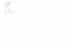
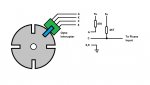
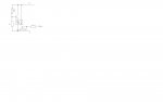
so i thought best idea would be to use the LDR to detect light though a slot in a old CD (attached to shaft) and then use a count command... well you get the idea. how ever i am not sure how how the count cammnd will handle the LDR being an anologue device. this is where i presume i will be needing at least the transistor. the idea is to make the signal apear as a simple 0 or 1 to the picaxe. i have drawn a couple of circuits. but dont know which one is going to be best, or if i have missed anything. its been a while since i messed with this stuff and it 2am
 

Attachments

Last edited:

techElder

Well-known member
There's no need for an opto-isolator in those circuits. The grounds are all common, and it's all low voltage.

What kind of count frequency are you expecting?
 

oracacle

Senior Member
it will eventually be for wind speeds. i think the idea is to have a CD mounted on the shaft of the wind speed thinging-ma-jig, so it depends on how the match works out. i think the circumfrence of a cd is 37cm. so i will go scratch my head with the aid of a calculator and see what i come up with - knowing my maths is will be and nuts figure and thus completely wrong
 

oracacle

Senior Member
OK, i just wanna make sure i got this right. there is 100,000cm to 1km, 100,000/37 = 2702.7 / 60 = 45 rpm for a wind speed of 1km per hour

so for 60kmh 45 * 60 = 2700 rpm. if i could higher it would great. i need to to some more research on the count or pulsin to find out what sort of limits there are
 

IronJungle

Senior Member
What I don't know about LDRs is a lot....
That said, it doesn't seem to me like the LDR would react quickly enough to work for this application.
 

lewisg

Senior Member
Hall effect sensors are commonly used for rev counters. There are two basic types, momentary and latching. The momentary ones pulse each time they are in a magnetic field of sufficient strength. The latching ones change state with reversals of the magnetic field. Momentary is more common for this sort of application but latching commonly uses two magnets which may help with shaft or disk balance.

A good hall effect sensor demo can be found here.

Reed switches are also popular.

For wind speed you are looking for an anemometer. I have been considering using one of these for navigation assistance on a boat.
 

buntay

Senior Member
I am doing the same thing, a little different setup and resolution, but thinking of using a laser and photo transistor.
A little skimming research seems like this would be the best bet,simpler schematics, but my concerns lie with how long would the laser last and the effectiveness of a focused LED over the laser.
Also its a given that it would have to be in a dark enclosure to keep out any ambient light.

Anybody play with this kind of a setup with picaxe?
 

MartinM57

Moderator
OK, i just wanna make sure i got this right. there is 100,000cm to 1km, 100,000/37 = 2702.7 / 60 = 45 rpm for a wind speed of 1km per hour

so for 60kmh 45 * 60 = 2700 rpm. if i could higher it would great. i need to to some more research on the count or pulsin to find out what sort of limits there are
I don't think so. The rpm of your CD depends on how fast your thing-a-ma-jig rotates in the wind. It's nothing to do with its circumference. Typically, you have to calibrate your 'jig at various known wind speeds - which of course you can get the PICAXE to do
 

oracacle

Senior Member
simple solution, make the circumfrence of the anemometer 37cm, providing it mounted on good quality bearings, the wind is going at 1kmh, it will turn at 1kmh.

how do you think that work out speed reading from motorcycle gear boxes (yeh alot them have speedo reading taken from the output shaft of the gear box)
also it works on the same set up as push bike speedos, the last time i set one up it asked for the rolling circumfrence of the wheel (inclusive of tyre). the rest is pure mathmatics.
in this case its not the engine or ground turning it at that speed but the wind

as for the other options. i may look into the reed switch, i did think about that for moment or two, how ever the balance issue with the magnet on the disc or shaft and also bounce on the switch at very high speeds. i could rig a test up with my dremel - slowest speed 17500rpm
 

nick12ab

Senior Member
If it's of any help, you can get sensors like those below from old printers which use them to detect rotation too.


bluejets

Senior Member
If it's of any help, you can get sensors like those below from old printers which use them to detect rotation too.

I agree.....use these all the time. Useful for not only pulse but also they are extremely accurate when use in a linear fashion. i.e the beam will make and break consistently within 0.001". Very easy to use, the resistor for the led is on the board. There are 3 pins, supply pos neg and an open collector transistor for signal. Run a 10K up to the positive rail from here (depends on what supply you are using) You may have to work out what connection goes where but they clip together so tracing out the circuit is not a problem. Just be aware that they are not all the same connections. You will just need the "black bits". Best part is, they are free and there are literally millions of them everywhere.
 

techElder

Well-known member
oracacle, it isn't the circumference of your disk that is important, it's the circ of the detection point. There are several ways to calibrate this kind of test instrument; one of them being mechanical; another being electronic. Your approach could use a mechanical calibration and a fixed program in the Picaxe.

You could take the mechanical adjustments out of the picture by fixing the mechanics down tight (designed to be a close approximation) and using adjustment procedures in your program to change the calibration. This is a much easier approach, because your anemometer will typically be mounted higher than your reach.

simple solution, make the circumfrence of the anemometer 37cm, providing it mounted on good quality bearings, the wind is going at 1kmh, it will turn at 1kmh.

how do you think that work out speed reading from motorcycle gear boxes (yeh alot them have speedo reading taken from the output shaft of the gear box)
also it works on the same set up as push bike speedos, the last time i set one up it asked for the rolling circumfrence of the wheel (inclusive of tyre). the rest is pure mathmatics.
in this case its not the engine or ground turning it at that speed but the wind

as for the other options. i may look into the reed switch, i did think about that for moment or two, how ever the balance issue with the magnet on the disc or shaft and also bounce on the switch at very high speeds. i could rig a test up with my dremel - slowest speed 17500rpm
 

RexLan

Senior Member
QSE114 Phototransistor (IR)
1.7V IR LED Infrared LED

Use 4 windows in your disk. Get a rolling average and you should have very good accuracy and resolution. Don't over sample and update maybe every 5-10 seconds max.

Circumference/distance are not important. A simple count will get the job done.
 

Goeytex

Senior Member
If slots are a problem you can superglue tangs to extend out instead.

Emitter ( Diode)
A = Anode
K = Cathode

Transistor
C = Collector
E = Emitter

Adjust value of 470 ohm resistor per device datasheet.
 

Attachments

Last edited:
Top