Help with an 08M!

VickiRoots

New Member
This is my first post so bear with me as I try to explain.

I am using an 08M picaxe in my 3rd year project at university. I have never used one before and was told by the technician that this one would be suitible for my needs. I have made my PCB and went to go write my program today when I noticed that it will not receive data via the serial in connection other than to program it in the first place.

I wanted to use this connection to constantly receive an input from MATLAB. I was going to use the serrxd command to do this, but now I find out that the 08m doesn't have this capability.

My problem now is I don't have enough time to redesign and make a new circuit for a different PICAXE as I only have 4 weeks left to finish the whole project. I was wondering if I could connect the serial in pin (leg 2) to the in 3 (leg 4) and use the serin command, still getting data in via the serial download cable. Currently my leg 4 is not being used but my current circuit could be easily modified. I wanted to know if this was feasible and would the picaxe work correctly? Any help would be appreciated!
 

Rickharris

Senior Member
To help we need more information. Your circuit, a photograph of your board and your programme will be a good start. As always crystal balls don't work so well over the internet :) - I am sure we can help if you help us understand what is happening.
 

BeanieBots

Moderator
Welcome to the forum.

Your description of the proposed mod to your board is a little vague.
As suggested by Rick, post a diagram to avoid any confusion.

The bottom line regarding the serin pin (leg2) is that if it EVER sees a logic high, the 08M will enter into a mode where it thinks it is about to get a new download and consequently reset.
Hence, you cannot connect serin and input 3 (leg 4) together but you could disconnect serin from the download jack and then connect input 3 to the download jack to receive data. The serin pin must not be allowed to float so you would need to tie it down to 0v.
 

hippy

Ex-Staff (retired)
@ VickiRoots : Yes, there's a relatively easy mod which you can make to achieve what you need. When I've sorted out my evening meal I'll be back ... stay tuned.
 

MartinM57

Moderator
...and a lesson to learn is not to make a PCB before you done a prototype/pre-production version of the system and it's been well tested.... :)
 

hippy

Ex-Staff (retired)
... after sorting out meals and waiting for my ISP to finish their unsolicited CM 'firmware upgrade' ....

What you have -

Code:
                              -.-   PICAXE-08M
                               |   .----__----.
               ___             `---| +V    0V |
RX >--.-------|___|----------------| SI    O0 |
      |        22K                 | X4    X1 |
     .|.                           | I3    X2 |
     | | 10K                       `----------'
     |_|
      |
     _|_ 0V
What you will want -

Code:
                              -.-   PICAXE-08M
                       1N4148  |   .----__----.
               ___    .--|>|---^---| +V    0V |
RX >--.---.---|___|---|--------.---| SI    O0 |
      |   |    ___    |        |   | X4    X1 |
     .|.  `---|___|---^--------|---| I3    X2 |
     | |       22K             |   `----------'
     |_|                       O-.
      |                        O-'
     _|_ 0V                   _|_ 0V
That perhaps looks a little complicated but is only the addition of a 22K resistor, 1N4148 diode and a link or switch. You may need to replace the 10K with 22K.

With the link open you can download new programs into the PICAXE. With the link closed you can receive data sent using "SERIN 3" commands. A bit of inconvenience having to change settings but hopefully not too much.

An alternative is, not to modify or redesign the board but to plug a different PICAXE in if you have room and the other I/O and ADC are suitable. Both 14M and 20M will fit in the 08M socket and support SERRXD. You can snap off the lower-end legs so while it will hang over the socket end it shouldn't short with anything.

It has been suggested that "SERIN 5" can work in place of SERRXD on an 08M. We do not recommend that and it may cause unexpected resets and other problems but you could try that at your own risk.
 
Last edited:

manuka

Senior Member
VickiRoots: I'm just up the road in Wellington, so may be able to "fellow Kiwi" assist when you outline just what your project actually does. My past experiences with final year projects indicate 4 weeks for a 08M project should still be feasible by the way. However this tends to relate to your specific field & skills! Stan
 

VickiRoots

New Member
Firstly let me thank you all for your help.

Manuka I think you must be mistaken, I live in Canterbury in England. I didn't even know there was a Canterbury in New Zeland, sorry for any confusion but thanks for the help anyway.

Also I think I maybe able to modify my existing circuit to use a 14M in the 08M socket as suggested by hippy as this means I don't have to modify my circuit, which I don't have time to do.

Also I do understand that a prototype may have been useful I do not have the time and the university does not have the resources for me to make a few prototypes, along with all the other electronics students! Sadly as I said this is my first time using PICAXE's as I will certainly read up on them myself next time instead of just taking the word of a technician. Clearly they do not know everything as I was lead to believe :)

But thank you all for your quick replies, you have been most helpful!:)
 

westaust55

Moderator
An alternative for initial circuit testing is to use a breadboard (the type with lots of holes and electrical connections internally :) ).
May not be cutting edge technology :rolleyes: but relatively cheap to purchase and easy/fast to change the circuit as required.
 

BeanieBots

Moderator
I do understand that a prototype may have been useful I do not have the time and the university does not have the resources for me to make a few prototypes, along with all the other electronics students!
Do you remember BEAGLE the Mars rover?
They didn't have the time or resource to test:mad:
Cost millions and they ended up with nothing because they didn't include the circuit diagrams when they send it up so the Marsians couldn't fix it:rolleyes:
That was just so embarrasing:eek:

The more limited the time and resource, the more ESSENTIAL the need for prototyping. It saves time and money in the long run. Only very well financed companies can afford the risk of design to production and even then it's only done under exceptional circumstances.
A simple circuit using breadboard only requires minutes to construct and it's a one-off cost for the breadboard which can be used over and over again.
 

slurp

Senior Member
The more limited the time and resource, the more ESSENTIAL the need for prototyping. It saves time and money in the long run.
Breadboards - one of the few products I buy from Maplin. They generally have a few instore, I like the size of their AD-100 (under £2) for 08 and 18 picaxes. If you like to have a power rail down the length of the board then there's the AD-101 but you double the cost!

Rev-Ed have them too and a nice little programming adaptor :)

regards,
colin
 

hippy

Ex-Staff (retired)
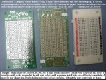
Speaking not so much as a 'salesman' but as someone who has spent their own money on tools for personal use, the PCB015 is a nice, compact but usable, breadboard, and for more permanent circuitry, PCB001 stripboard and the PCB005 striboard track cutter are good value as well.
 

papaof2

Senior Member
Speaking not so much as a 'salesman' but as someone who has spent their own money on tools for personal use, the PCB015 is a nice, compact but usable, breadboard, and for more permanent circuitry, PCB001 stripboard and the PCB005 striboard track cutter are good value as well.
Breadboards, especially when used with a protoboard, are one of the best investments you can make. A prototype takes only minutes to build and changes take only seconds - you can get an answer to "What if I change ...?" faster than if you posted on the Forum ;-)

I have 08 and 18 protoboards from Peter Anderson, each with a 400 pin breadboard attached over the protoboard area. I also have 3 of the 400 pin breadboards for "add-on" items (display, etc) and a 1200 pin breadboard on a case which includes a regulated 5 volt supply (built in the days of 7400 series logic). That probably sounds like overkill to a novice, but the 400 pin breadboards are only $4US from All Electronics http://www.allelectronics.com/make-a-store/category/105/Breadboards/1.html

John
 
Last edited:

slurp

Senior Member
PCB001 stripboard and the PCB005 striboard track cutter are good value as well.
Definately, stripboard with a few header pins can make a neat daughter-board too, especially for those parts of the circuit that are fixed or you want to re-use between breadboard test circuts.

I have used a drill bit to improvise track cutters but a handle is much easier on the fingers! More recently I moved to using a stanley knife to cut the tracks, this aides closer positioning of components as you do not need to use one hole pitch for the break.... might be clearer if I upload a picture later!

regards,
Colin
 

manuka

Senior Member
VickiRoots: Whoops- wrong country indeed! NZ's Sth Island has a large province called Canterbury,with an esteemed university of the same name. Christchurch is the main city.

BB: Well said.

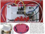
To spare forum readers with delicate dispostions I'll not elaborate on my own long standing breadboard enthusiasm. However probably only 1 in 10 of my initially prototyped circuits now ever gets to the PCB stage. Given productivity aids such as the nifty jumpers shown below, designs can be rustled up in a flash- even away from specialist facilities.

With breadboards so cheap & convenient, many working circuits (especially 433 MHz) may remain on their breadboard for months, & increasingly they'll go the soldered "Kiwi Board" way even when being field tested.
 

Attachments

Last edited:

Peter M

Senior Member
Hippy@ is it possible to use another pin (like pin 4 for example) to ground the SI pin or have I missed something. A simple code to wait on startup could allow for programming, then it switchs to ground to go into matlab receive mode?

everyone else @ wow that was a quick change to breadboards.... I have to agree though it is the easyest way to proto type
 

hippy

Ex-Staff (retired)
is it possible to use another pin (like pin 4 for example) to ground the SI pin

I have a vague feeling of deja-vu so it may be a re-discovery of a known idea but it's an interesting question, it looked feasible, so I tried it, and it works !

The key with serial split to SI and a SERIN pin is in keeping SI at 0V while running to prevent data received causing a download / reset but not affecting SI while downloading. As pin 4 is input on power-up it fulfils the later, and after "LOW 4" achieves the former.

Linking SI to Pin4 and a "LOW 4" at the sart of the program is all that's needed to save having to have the manual link. The only downside is that all downloads would have to be done using a Hard Reset ( power off, then power up after initiating download, so the PICAXE hasn't executed the "LOW 4" and disabled download ), but as code waiting on a SERIN often requires that anyway it's probably no extra inconvenience.

As SI and pin4 are adjacent, a 0.1" molex link can be fitted so it would be easy to disable this behaviour if required for other programs by removing the link.

#Picaxe 08m
Low 4
Do
SerTxd( "OK " )
Loop

Without linking SI to pin 4 the program can be re-downloaded at any time while that program is running. Once SI and pin 4 are linked, download only works with a hard reset.

This should also work with any pin which defaults to input at power-on which can also be set as output low.
 

Peter M

Senior Member
Thanks....... and as usual you have expanded on the idea making it even more versatile.

(I was just thinking of a solder bridge)
 
Top