Robo_Maker
New Member
Hi all,
I am trying to create my own robot based on AXE118 project board using SRF05 ultrasonic range finder.
I managed to connect the SRF05 to microbot B120 and it works very well. However, I am not successful in connecting the same SRF05 to AXE118 board.
The only difference I spotted in 2 schemas is that B120 is using R220 on I/O to the microprocessor, while AXE118 has some resistors array.
Also, I connected LK1 on AXE118 and tried both RPU and RPD positions on AXE118 with no luck. I debug with the serial cable and buzzer (on B.1 on AXE118 ).
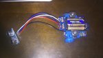
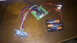
Please see both of my wirings on attached pictures:
pic1. Not successful to AXE118 - I connected to the same C.1 and C.2 as on B120 to use the same code
pic2 Successful to B120
This is the code I used for both units:
Your advice is very needed!!!
Best Regards,
I am trying to create my own robot based on AXE118 project board using SRF05 ultrasonic range finder.
I managed to connect the SRF05 to microbot B120 and it works very well. However, I am not successful in connecting the same SRF05 to AXE118 board.
The only difference I spotted in 2 schemas is that B120 is using R220 on I/O to the microprocessor, while AXE118 has some resistors array.
Also, I connected LK1 on AXE118 and tried both RPU and RPD positions on AXE118 with no luck. I debug with the serial cable and buzzer (on B.1 on AXE118 ).
Please see both of my wirings on attached pictures:
pic1. Not successful to AXE118 - I connected to the same C.1 and C.2 as on B120 to use the same code
pic2 Successful to B120
This is the code I used for both units:
Code:
#terminal 9600
main:
pause 100
	pulsout C.1, 2
	pulsin C.2, 1, w0

	w1 = w0 * 5 / 58 ; Convert to cm
	w2 = w0 * 5 / 148 ; Convert to inches

	sertxd("Distance is ", #w1, "cm",CR,LF)
	sertxd("Distance is ", #w2, "inch",CR,LF)

	if w1 < 20 then
		sound B.2,(50,100,100,100)
	end if
goto mainBest Regards,
Attachments
-
 649.4 KB Views: 26
 -
 723.6 KB Views: 26
Last edited: