johnmobley
New Member
I am wanting/trying to control some 12VDC LEDs via PWM using a PICAXE 14M2. What is the best method to do this. Working with PWM and LEDs is not new to me but trying to control them at higher voltages is new for me.
'loop RGB LED Control
'May 2012
'Picaxe 14M2
#picaxe 14m2
#No_Data

symbol counter 	= W2
symbol Green	= W3
symbol Blue 	= W4
symbol loopcount	= b0

symbol Redout	= b.2
symbol Blueout	= c.0
symbol Greenout	= b.4

dirsb=%00011111
dirsc=%00000111
pwmout Redout,100,0
	pwmout Blueout,100,255
	pwmout Greenout,100,0
main:

gosub fade
'
goto main


fade:

	for counter = 0 to 255
		  pwmduty Redout,counter
		  w5 = 255-counter
		  pwmduty Blueout,w5
		  pause 10
	 next counter
	 pause 400
	 for counter = 0 to 255
		  pwmduty Greenout,counter

		  w5 = 255-counter
		  pwmduty Redout,w5
		  pause 10
	 next counter
	 Pause 400
	 pwmduty Redout,0
	 pause 200
	 for counter = 0 to 255
		  pwmduty Blueout,counter
		   w5 = 255-counter
		  pwmduty Greenout,w5
		  pause 10
	 next counter
	 pause 400

	for counter = 0 to 255
	 w5 = 255-counter
		  pwmduty Blueout,w5
		  pwmduty Redout,counter
		  pwmduty greenout,counter

		  pause 10
	 next counter
	 pause 400
	for counter = 0 to 255

		  w5 = 255-counter
		  pwmduty Blueout,counter


		  pause 10
	 next counter
	 pause 400
'	pause 50
'
'
'pwmout Redout,off
	'pwmout Blueout,off
	'pwmout Greenout,off
	return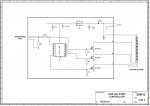
- 20mA is a lot for an led indicator, you might be happy with 10 or even 5. These could also be in series. The leds might be connected across the switch contacts but might be separately powered, worth considering the options.
- leds generally don't need 4 - 5 volts. Try a sample and see what they drop at the desired current. Constant current is a much better way of thinking about them. But a series string would work. Consider more than 12v if you need long strings, connected via a pwm-driven constant-current supply.
- Mosfets for pwm switching are necessary, even better 'coolfets' with lower on resistance. Most mosfets/coolfets need a driver chip to ensure a high enough gate switchon voltage (logic level ones may not). Picaxe fed from 5v, driver and mosfet from 12v (or higher).
- depending on layout, cable capacity may be an issue due to voltage drop at high current, and little voltage to spare.
My kitchen lights are all 12v led units driven in this way from a 12v (car battery) supply with push-button control and pwm for reduced level settings.
search for SPP20N60C3 from Infineon