H Bridge horrors

mdunk

New Member
Hello, a little help is needed.

I am THAT close to completing my picaxe solar tracker. Thank you to forum members who have helped me solve my EEPROM programming problems, my i2c interfacing and my potentiometer problems.

So, I got everying working nicely, with indicator LEDs sitting on the ouputs of the picaxe 18x where I planned to put the H Bridges that will control the rather power hungry tracking motors. All work well, things light up when they should and I can pretend to be the tracking motor, moving the potentiometers to simulate the panels moving and the circuit then turns the indicator LEDs of when expected. I THOUGHT I could do the HBridge bit myself, but I am stumped.

I don't have the tools to produce a ledgeable circuit diagram, but it is simple enough to describe.

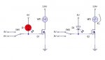
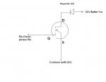
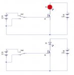
I have connected Output 0 of the picaxe 18x to the G connection of a MTP3055VL mosfet, (just the first one of the four that will make the H Bridge for testing purposes only at this stage). I have connected the S pin of the mosfet to 0V ( the common ground rail for everything, including the picaxe chip) and I have a separate test battery (3.6V) and diode connected to D and the common ground simulating the tracking motor.

So now the odd bit. When I set pin 0 high, my test LED goes OFF, when I set it low, the test LED goes ON. This is exactly the reverse of what I expected! Even stranger still, if I turn the picaxe supply power off, the test LED goes off too, which is doubly odd as I would have thought that was the electrical equivalent of setting pin 0 low, but I understand that such assumptions do not always hold with picaxes.

So my question is... is this what SHOULD happen? Is my understanding of mosfets completely back to front? I thought putting the G pin high "turns the mosfet on" in a manner of speaking, but quite the reverse is occuring.

Or do I have the wrong sort of mosfet?

Help please.

Matthew:confused:
 

Andrew Cowan

Senior Member
I assume you have connected the LED between pin 0 and +V. This would cause this to happen - output pins act as a 0V line when at 0.

Is my circuit diagram right?

A
 

Attachments

Last edited:

demonicpicaxeguy

Senior Member
i would use a pulldown resistor on the gate pin, that way the pin doesn't "float" when power is turned off (a little dangerous on a h bridge)

and a diode between the picaxe and the mosfet, stick the diode closer to the picaxe rather than the mosfet,eg somthing like:


*nb forgive any errors in image, drew it in a hurry
 

mdunk

New Member
I really MUST install some circuit drawing software!

Please excuse this poor effort, MSPaint is not exactly a circuit drawing package. I think I drew the LED back to front too!

Anyway, this should convey what I have done so far.

To clarify, the only LED at this stage is one that is designed to check if I am succeeding in turning "ON" the mosfet. I know pin 0 from the picaxe is going high through previous testing with leds and a quick check with the multimeter.

So, the LED sits between D on the mosfet and the 3.6V battery, and I expected it to turn on when I set the G pin high on the mosfet using the picaxe, however exactly the opposite occured!
 

Attachments

demonicpicaxeguy

Senior Member
try this out to test the mosfet


put a 10 resistor between the gate and 0v
connected up your led and your multimeter
then manauly switch the gate on and off with another piece of wire, see how it reacts

i assume you've got this on a breadboard?
 

BeanieBots

Moderator
Your operation assumption is correct but your observed behaviour is not.
This would suggest one of two possibilities.

FET wired incorrectly. Check and double checkyour circuit pin assignments.
Damaged FET (could be caused by static from poor handling methods) resulting in short between gate and drain.
 

mdunk

New Member
Thanks all, a bit to do there. At least I don't seem to have misinterpreted the device completely. Too late to start soldering tonight, I will try soldering up again tomorrow, and yes, I have some more of them, so if the current one keeps doing what it is doing, I will try with some others.

thanks for the help so far, fingers crossed for tomorrow evening.
 

Dippy

Moderator
Mdunk, get yourself a dollop of plug-in breaboard.
This sort of thing is SSSOOO much easier with breadboard.

If you haven't seen what it is then I'm sure someone will post a picture.
 

mdunk

New Member
Thanks Dippy, a very good idea, I am going to do just that, AZTronics here I come!

I have been going along really nicely with vero board so far, not one single problem connecting up the power regulator circuit, a picaxe 18x, a clock chip and and eeprom, plus half a dozen diagnostic LEDs.

But I think I might have jinxed myself when I decided it would be much neater to build the H Bridges on a separate Vero board and connect the two with a pretty ribbon cable (lots of lovely colours!)

Must have used up all the good luck on the first vero board.

The real irony is that the H Bridge was supposed to be the EASY bit!

Fingers crossed for this evening, with the breadboard FIRST.
 

mdunk

New Member
Mdunk, to get a better handle on sketches, download the FREE Expresspcb software. Use the ExpressSCH program to do your sketches.......

http://www.expresspcb.com/ExpressPCBHtm/Download.htm
John, I went to download the program you suggested, and suprise suprise, I had already downloaded it, I had just never got around to INSTALLING it. Given I stored it in my picaxe forum files folder, I have a funny feeling someone else on the forum might have recommended it also.

I will INSTALL it this time, thanks for the tip.

M
 

jglenn

Senior Member
Is that an N channel fet? Are you sure S and D are not switched?

Why don't you have a resistor in series with the led? Is it an Rled.

Your schematic should work, there is no inversion that should occur.

Try it with a switch, instead of the picaxe on the gate. You should have a
pulldown resistor on the gate, even 100K is good. This way if nothing else
is connected to the gate, it will keep the fet off.

ALSO, did you tie the grounds of the 3.6V batt with the picaxe supply???:confused:
 

mdunk

New Member
Hi jglenn.

A few things there. I finally got in to AZTronics today, and picked up a breadboard as per suggestions so I am ready to test. On a side note, they also had some very cheap (A$11) LCD displays that should work on the I2C bus, but apparently there have been picaxe fanatics in there already cleaning out the supply, so that's probably not news to anyone here.

Anyway, to address your points..

Is it N channel? Well, yes, according to datasheets I found on the web, and according to the pin diagram on the datasheet I have D and S the right way round, although I did find remarks in other discussions about one version of the mosfet (Motorola?) having a different pin order. Funnily enough, I mentioned my problems at AZTronics this morning and they went straight for their computer to check that it was N Channel too. Their computer seems to think so...

No, I did not have a resistor in series with the led (oops), and I should have, I completey forgot. I will add one, I can't remember what to use, but I have plenty on the board already for reference.

Now I have the breadboard I will do all of the initial testing without risking blowing up my picaxe. The thing is, I just got a bit over confident, everything was going so well up till now.

Finally, yes a pull down resistor is a very good point, I forgot that too. I think, in my defense, I left it too long between doing all the reading, research and building on the picaxe and starting the H Bridge, so that by the time I started the H Bridge, I forgot all the points about pull down resistors etc. This is first real bit of circuitry I have ever done, and a lot of the learning is yet to "stick". Time to slow down and THINK a bit more...

Also, I plan to try out the LCD tonight, just in case. At $11, if I can make it work I will buy 10 more!
 

jglenn

Senior Member
I am interested in that I2C LCD, post a link to the source and data sheet if you can.

You did not answer if you tied the ground of the 3.6V batt powering the output circuit to the ground of the PICAXE 5V supply, that is critical. As a circuit detective, I cannot discern how you got an inverted output. When the fet gate is high, of a n channel, grounded source, the drain will be pulled low, and the led should be on.

Fets are easy. I like the ZVN4206A. Also use the NDS9936 which is 2 5A fets in an SOIC package, not too hard to solder. They have low on resistance unlike old fashioned NPN's. :p
 

mdunk

New Member
Hi Jglenn,

Sorry, I forgot to answer that rather salient point. For once, I can say, I got that bit right. ONE bit of important info that has been hammered into me by just about everything I have read on using Mosfets is the importance of a common ground. Something that is anything but intuitive to a circuit newbie, so thank you for checking.

As for the datasheet, the closest I have found yet is:

http://www.jeanlcd.co.kr/product/JA-16202.html

Not sure that it is exactly the same product, my product code reads, in full...

JA-SCB1602S-GN12M-LB and it is certainly from JE-AN Electronics.

The picture on the jeanlcd website looked promisingly similar, and there is the right number of pins etc, but among things I could not see on my first glance was any addressing information for the I2C bus, which is a bit critical. AZTronics mentioned that someone else with a keen interest in picaxe chips was tinkering already. I am VERY unlikely to beat them to working out how to drive it with my somewhat limited experience, but I am hoping to get it working without asking for help. I can dream...
 

mdunk

New Member
JGlenn,

On the matter of the choice of Mosfet, I have to switch some pretty big currents, the North-South motor draws more than 10amps at 24V (The array does weigh over 250kg), though the East-West motor is only using 2 or 3 amps at 12V. I would love to have found a package that did all the bridge work for me, but I could not find one that handled the range of currents, plus I think the Nort-South might spike up a bit over 10 amps at startup, though I do not have the equipment to track that accurately.

Do you know of a package that could do it for me?

Matthew
 

BrendanP

Senior Member
H Bridge-Scourge from Hell

Matt, H bridges are a pain in the neck. I did a lot of work with them for motor control and found them at best temperamental. I fried lots of H Bridge drivers, pcb tracks and bread boards.

I instead choose to use a DPDT relay and a transistor under pwm. The relay does the direction control and the transistor does the speed control. A 08M will run the thing for you nicely. Its rock solid, never suffers from shoot through. You turn off the transistor, throw the relay and ramp up the pwm to the motor in a for..next... loop. You can get nice smooth stops and starts.

You could use a high current transistor in a TO3 case. Give yourself heaps of margin, that's how I like to do things anyway, you want the tracker to work for years without trouble.

Try it, its the go.
 
Last edited:

demonicpicaxeguy

Senior Member
Matt, H bridges are a pain in the neck. I did a lot of work with them for motor control and found them at best temperamental. I fried lots of H Bridge drivers, pcb tracks and bread boards.

I instead choose to use a DPDT relay and a transistor under pwm. The relay does the direction control and the transistor does the speed control. A 08M will run the thing for you nicely. Its rock solid, never suffers from shoot through. You turn off the transistor, throw the relay and ramp up the pwm to the motor in a for..next... loop. You can get nice smooth stops and starts.

You could use a high current transistor in a TO3 case. Give yourself heaps of margin, that's how I like to do things anyway, you want the tracker to work for years without trouble.

Try it, its the go.
thats pretty much what i've done on my cnc mill,
the only thing is that i've now got to stick in a circuit for the electro magnetic braking
 

mdunk

New Member
Great, now I am confused. :confused:

I was thinking that using an H Bridge and staying purely solid state to avoid moving parts, such as relays, would be more reliable. But if the H Bridges turn out to be unreliable I will have gone through all this for nothing!

I don't need to do speed control, basically on and off will do the work, so a relay would be VERY simple indeed. Plus, the really big tracking motor is actually from an electric wheelchair, so it has a very nice electromagnetic braking system built in if needed. (Not that I think it will be needed)

I will file your thoughts, and keep up with the H Bridge (I bought a lot of Mosfets, I might as well try them, if only for the fireworks) and if the bridges keep dying I will go back and try the old fashioned relay option.
 

BeanieBots

Moderator
I fully agree with BrendanP.
Unless you are very experienced with driver circuitry, a high power H-Bridge will be very difficult to get right.
Either get a ready-made module (which are not cheap) or use the method described. Namely a single PWM'd transistor and relay for reversing. Even then, you will need some form of driver for the power transistor.

EDIT: After reading your last post which crossed with mine.
If you don't need speed control then use relays. Unless you fully understand about FET driving methods and back emf issues, it will be a lot more reliable Assuming you spec the relay correctly.
Don't forget, when a motor is turned off, there will be a large back emf voltage which can easily destroy a FET even if it's rating is >100v. When choosing a realy, check the inductive load rating. It will be much lower than the DC resistive rating for both voltage and current.
 
Last edited:

mdunk

New Member
Who would have thought relays would turn out to be so popular in what is essentially a solid state community!?

I do have lots of really BIG diodes to protect my mosfets from EMF back surge stuff, but I starting to think I am kidding myself from the reactions around here...

My problem is, after years of driving antiquated European cars I have a slightly paranoid approach to relays, which are nearly always the reason the car did not start, the windows would not open or the wipers did not come on the one day it actually RAINED in Adelaide.

To me, a relay is a device for permanantly interrupting power supply at the most inconvenient time possible. I think the best example is the piece of crud that shut down the fuel injection on my 1990s 2.5 ton Range Rover on the lowest level of a 5 story underground car park. Delightful experience that, no headroom to tow the car out, and a very underwashed car park attendant breathing down my neck while I groped around the engine bay in semi darkness trying to isolate the fault with a $20 dollar multimeter, a $2 torch and piece of coathanger wire. (Don't ask, just think VERY slow blow fuse.)

Mind you, they do call Lucas electrics the prince of darkness...

Can anyone recommend a RELIABLE relay brand? Bosch?
 

BrendanP

Senior Member
I was sold on relays when I read in the Mouser catalogue that car manufacturers use a relay they sell for their power seat opps.

With respect to BB I think you will need the transistor even if you dont want speed control. You need to be able to stop the power going to the motor somehow?

By using PWM you will be able to slowly apply and stop power to the motor moving your array, a "soft start" like you get on power tools. This will make the motor last much longer and will be easier on the array itself and its support structures, reduced metal fatigue. Stop the array bouncing around

Once you get going you could put a low side current sensing R on the motor which the picaxe would monitor and then if the motor was drawing a lot of current you could stop the motor, maybe the motor was jammed or had very high wind loading.

The picaxe manual shows how to use a transistor to switch the relay and use a diode to prevent back emf damaging the q when the relay coil is denergised.

Throw the parts you have in the odds and sods box and get a relay and big mo' transistor.
Everyone on this forum will have lots of parts they have bought for projects and then went a different route and didnt need them. You can use them for something else.

Time is more valuable than parts.
 

BeanieBots

Moderator
Who would have thought relays would turn out to be so popular in what is essentially a solid state community!?

I do have lots of really BIG diodes to protect my mosfets from EMF back surge stuff, but I starting to think I am kidding myself from the reactions around here...

Can anyone recommend a RELIABLE relay brand? Bosch?
Point proved, a BIG diode is less likely to protect your FET than a small one. It needs to be fast, BIG often (but not always) means a large junction which often (but not always) is slow to react and the voltage spike gets to the FET before the diode starts to conduct.

Anyway, take the relay route. It will save you lots of headaches.
Relays are very underestimated and very reliable when used within their spec. The most common failure in cars is falling out of the socket due to vibration and/or contact melt due to a failed driven device. When a motor fails short and pops the fuse, it will have over-rated the relay as well. I wonder how many people replace the relay or even check it?

Which is the most reliable, relay or FET?
Ans. Relays are used in safety circuits far more than FETs.

Omron relays are very reliable, but just as with any component, only when used within spec. However, a relay will tollerate far more abuse outside its rating than any semiconductor could ever dream of coping with.
 

mdunk

New Member
Yes, a the low side resistor sounds good, I have incorporated timing loops to detect if things have jammed, but that sounds a little more sophisticated.

Bounce at the mechanical level should not be a problem, I am driving a threaded rod in one case and a very low geared slow winch in the other, so movement is at the rate of continental drift, but I take the point about strain at the motor level.

I will have another look at the manual with regard to the relay driving the transistor... I would have thought it was the other way round? Suprising that.
 

mdunk

New Member
And as for relay failures in cars... with due respect to the English contributors, the most common cause of failure of a relay in an English car is being made by Lucas and being attached by Rover.

Lovely car to drive, and it would go absolutely ANYWHERE in princely comfort, but the electrics were really something else.
 

BrendanP

Senior Member
I am using these at the moment.
http://au.mouser.com/Search/ProductDetail.aspx?qs=PQE8scD4k1xQoMZ8gf4XfQ==

Your app. might need more amp handling ability however.

A lot of parts you see at Jaycar, Dick Smith, Altronics etc. are rubbish.

You want brand names like Tyco/Shrack, Bosch, Omron etc.

I like to buy from Mouser because they don't sell amateur, hour crap parts manufactured down to a price and not up to a standard. Goto ebay if you want them.

Dippy loves to shop for all his part needs on ebay. Just ask him.

I just PM you Matt.
 
Last edited:

BeanieBots

Moderator
No offense taking as I'm well aware of British car reliability issues, however, if we're going to be pedantic about it, the deeper cause is when accountants get involved with design:mad:

"OK, I hear you, stop going on about it, will it work when it leaves the factory?"
 

mdunk

New Member
Hmm, yes that one would be a bit small, but I see plenty of others on the site that will work ok, if I jack up the coil voltage. No problem there, I can use the mosfets I just tipped into the spares box.

Now.... where did they go...?

Ebay vs that site, I would probably go for the site you provided, only because I always recommend that people should know what they want when using ebay, and clearly I don't clear that hurdle yet.
 

mdunk

New Member
No offense taking as I'm well aware of British car reliability issues, however, if we're going to be pedantic about it, the deeper cause is when accountants get involved with design:mad:

"OK, I hear you, stop going on about it, will it work when it leaves the factory?"
Ahhh, is that what killed the Range Rover? Like I say, a great car otherwise, and I bought it knowing full well that the electrics were a bit fussy, on the reasonable logic that at least I could fix the electrics myself and the mechanicals were absolutely bullet proof. I sold it to a nice young man with 300,000km on the clock and still going strong, even if the clock was not going so strong... but that was a different clock.
 

demonicpicaxeguy

Senior Member
No offense taking as I'm well aware of British car reliability issues, however, if we're going to be pedantic about it, the deeper cause is when accountants get involved with design:mad:

"OK, I hear you, stop going on about it, will it work when it leaves the factory?"

funny this comes up, my grandfather used to work at ford and later gm around the same time as the war, and he was always saying how that when the accounting dept and the "sytlists" got to work, the entire car would change from an engineering master piece to the "marketing dept"'s dream,

"many a brilliant engineering idea has been shot down some stylist" was what he used to say
 

mdunk

New Member
Oops, got all distracted by cars there.

I thought I should finish this thread by reporting back on the mosfet issue.

First, my thanks to Dippy for the recommendation of the breadboard. What a brilliant tool! Plus, I can finally involve my 7 year old son in some building and testing and he loves it.

Second, full points to BeanieBots, the mosfet was fried. I have 8 in total, and in a fit of zealous overenthusiasm, I had soldered all 8 neatly to the vero board in preparation for wiring them up. After carefully unsoldering them and using the breadboard I have discovered that I have managed to fry two of them, including the one that I initially tested.

Of the failures, I observed the following interesting behaviour...

The first one, the one described initially, is working almost perfectly in reverse. i.e. set G high and the D and S go open circuit, set G low, and D and S close, albeit with some resistance as the test LED is noticably dimmer than it should be.

The second fried mosfet is simply permanently closed on D and S, with no apparent resistance to current flow.

So thank you all for your assistance, it has been VERY educational.

(And thanks also to the British for making what was otherwise a very nice car to own and which I will miss on all but the wettest of rainy days. And yes, I totally agree with the sentiments of accountants getting involved in ANY manufacturing process, as exemplified by my attempts to buy a decent quality potatoe gun as against a $2 supermarket version. I would happily pay $20 for one like you used to be able to purchase, after saving carefully for months. But no, some bean counter decided it would be better produce something cheap with the kick of an aneamic butterfly that expires after ten minutes use. Rant = OFF.)
 

jglenn

Senior Member
You really need a current limited power supply. Besides a voltage adjust knob, there is a current limit knob. You can set it by shorting out the supply and turning it until the max current you want to run at is on the panel meter.

When trying new circuits, turn it down to 50mA or so. This will prevent blowing things up. Turn it up as required.

I use one like this, but only has one 2N3055 pass transistor. The LM10 may be hard to get these days, but there are circuits that use normal opamps.

http://www.powersupplycircuits.net/050V02apowersupply.html
 

BeanieBots

Moderator
Good advice from jglenn about power supply. An essential for prototype work, especially when using easily shorted/miswired breadboard.

A drain to source short is most often caused by excessive current melting the junction. However, your device which exhibits 'strange' behaviour sounds more like static damage or excess heat damage from your soldering iron. This is why good care needs to be taken with static precautions. The symptoms you see are extreme enough for you to know something is wrong. In many cases, static damage can be far more subtle and only manifests as a catestrophic failure several months (or even years) later on after the 'product' has been fully commisioned.
 
Top