Generate short circuit

MORA99

Senior Member
Hi,

After spending some time with different platforms, I have a project where PICAXE seems a good solution.

T-hansen in Denmark sells an "electronic launch system" for fireworks, which I want to make a better control box for (instead of the somewhat unreliable infrared one they provide) for next year.

I will use their fuse system, which is 5 fuses that ends in a standard 2x5pin array.
(A "fuse" is fitted with a clamp, which is attacted to the fuse on the fireworks, when shorted it makes a spark and ignites the fireworks, when the firework fuse is gone the clamp falls off.)

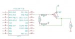
Upon startup I will need to see which fuses are avaliable, its fairly easy as its basically a wire, so I provide 5V an check that the picaxe can see this on another pin.

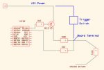
The problem is when I want to use the fuse, I have to make a short over the 2 wires, it will use about 350mA at 5V for 2seconds, so I need to protect the picaxe from this.

One way could be to use a 4051 and then select an empty port when ready to fire.
But maybe some diodes, (poly)fuse or resistor is easyier ?

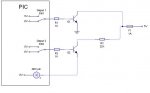
My basic idea is to provide +5Vdc on the fuses at all times, then use an tristate port on the picaxe to first sence the 5V and mark the port ready or blown.

Then change the port to HIGH and send it trough an transistor chip (ie. 2803A) to provide the short circuit.


Any ideas is most welcome :)
 

Dippy

Moderator
Well, you're going to get some gloom'n'doom merchants replying to this.

Sounds fun, just take care.

But I am confused by the fusing description.
A short? A spark? In my book 350mA is not a short.

Have you got a spec for the fuse?

But, in any event, I would probably do PICAXE O/P - trasistor/diode - relay -- fuse thing.

A fat bunch of batteries would easily handle 350mA and still provide power OK to PICAXE.
I would however have a generous decoupling cap by the PICAXE power pins as a glitch filter. Maybe even RC the PICAXE supply if there is sparkies kicking around.

But all your talk of 4051s has made me wonder whether this is moe complicated than the description.

Maybe a schematic would help us.
Maybe someone here, who hasn't got a train set, knows about pyrotechnics??
 

BeanieBots

Moderator
Yep, doom/gloom, safety and all that. False trigger prevention??

Detecting fused or not is simple. Pass low current and check for voltage.
"Correct" fuse will give "correct" voltdrop. Easily tested with ReadADC.
"Short" will give 'lower' voltage than "correct" fuse rating.

Of course, you'll be using a purely resistive current source to prevent contact sparks but then you would already know stuff like that before taking on such a project so no more needs saying about the safety side of things.

Also, active HIGH controls, NOT active low (such as 2803) to prevent 'ground' shorts causing false trigger. This is the opposite to safety interlock convention for obvious reasons.
 
Last edited:

Dippy

Moderator
Blimey, BB has overtaken me on the irony side.... ;)

"Any ideas is most welcome"
... I remember someone once said (of projects like this):
"If you need to ask then you shouldn't be doing it."

Hippy would want to know if you've done a full "risk analysis" , the level of "mission criticality" and whether you are fully insured ... he loves things like that :) and I'm sure he's got a dozen more Blue-Sky-Thinking phrases he can get into a reply (haha come on , it is Christmas!).
I'm sure he could even squeeze 'State Engine' and Interociter in there too!

You could just use a match and the next door neighbours young nephew....
 

premelec

Senior Member
As someone who lost an eye and part of my hand 60 years ago from a small amount of pyro material I'd make a suggestion that you NOT leave any voltage on the fuse but instead POLL the fuse with a low current to see if it's blown w/optoisolation - generating the current pulse could be done with optoisolators and triacs if you can use AC to blow the fuse... or DC triac with a very slow charge capacitor [well below triac holding current]. In any case you need safety switches to keep all current away from the pyro devices while installing 'em. Remember that things like two way radios can generate signals which make electronics do strange and unpredictable stuff... as can static discharge from fingers... so everything to the fuses needs to be left disconnected until everyone is well away and the lines from the fuses should be shorted at the control end before they are connected for safety... note that a cell phone is a two way radio ;-) Take care - I like pyrotechnics - safely.
 

MORA99

Senior Member
The fuse part is just a clamp with a small wire, which, when shorted, heats up fast and burns out in 2 seconds, which ignites the fireworks.

My system will not be less secure than what is being used as default.
All fireworks will be connected before power is applied, and in my final solution the control panel will be further away than the current IR solution allows.

In any event this is alot safer than igniteing it with a lighter and running away :)
It will not be left out when not in use, but mounted a few minutes before being fired, and power only applied when its ready to be fired and eveyone is at a safe distance, just like when igniteing it manually.


In the final version power will be supplied on the same cable that will control the fireing, so a switch can easily kill the whole box and all fireworks it controls (up to 5 things).

And ofcause safety switches on the main box to secure it from fireing again before a reset.

I have tested that I can run power trough and measure it with a DMM, and used my lab supply to see how much current is drawn when the fuse burns (without fireworks its pretty harmless).


I am wondering if a large resistor is enough to protect the picaxe from the 2sec short circuit.
If I didnt need to test which fuses is working, I could just use a relay, but since I need to test all 5 pins first, I need a direct connection at some point, and that connection must have some protection so the picaxe is not exposed to the short.
 

MORA99

Senior Member
Have you got a spec for the fuse?

A fat bunch of batteries would easily handle 350mA and still provide power OK to PICAXE.
No spec for the fuse, the original system uses 3xAA (4.5V).

A few pictures from the shop
http://media.thg.dk/DAT/pic/m/9875_1.JPG
http://media.thg.dk/DAT/pic/m/9875_2.JPG
http://media.thg.dk/DAT/pic/m/9875_3.JPG

And if anyones interested, heres how the original works.
1: Hold setup for a few seconds, led lights up and stays lit
2: Power on the control box
3: Point remote at the box, press setup once
4: Box shows which fuses are avaliable for a short time, then lights those leds in sequence for 12 seconds (cant fire untill this time is elapsed)
5: Avaliable fuses flashes to indicate they are ready to fire.

6: When fire on remote if pressed, the first avaliable fuse is used.
Repeat untill all fuses is used or press stop
7: When stop is pressed the control box enters safe operation and cant fire untill reset, the remote removes the pairing and the setup process has to be repeated before it can control anything again.
 
Last edited:

sghioto

Senior Member
MORA99,
Correct me if I'm wrong. You want to build an igniter control system with the firing box at the fireworks location and a remote control box connected by a cable. You have 5 igniters connected and want to verify continuity by means of a LED for each channel on the firing box and the remote control box. On the control box a seperate firing switch for each channel plus a possible ( just one ) momentary in-line "safety" switch. The system will operate on 5 volts. Is that about it ?

Steve G.
 

MORA99

Senior Member
MORA99,
Correct me if I'm wrong. You want to build an igniter control system with the firing box at the fireworks location and a remote control box connected by a cable. You have 5 igniters connected and want to verify continuity by means of a LED for each channel on the firing box and the remote control box. On the control box a seperate firing switch for each channel plus a possible ( just one ) momentary in-line "safety" switch. The system will operate on 5 volts. Is that about it ?

Steve G.
Yes, I just want a warning/status led on the fireing box, it will be close to the fireworks, about 3-5meters is all the fuse cable allows.

I will then use a control box further away 25meters or so to control it.

I want the following on the control box.

Master switch, keyed or "rocket switch"
Switch on the cable to the fire box (just hardware to cut all 4 lines)
5* leds to indicate state of each plug (working, used, active) (*red, yellow, green so 2pins each+gnd)
5 buttons to fire, when a button is pressed, a fire command is sent to the remote location, remote box will be unresponsive for the next few seconds while it fires the fuse and turns off the output again.


On the remote box I just need a on/off switch and a status led.

And yes everything on 5V, after new years eve, I will check how the original is made, I have a year to make sure this system works and is safe...
 
Last edited:

Dippy

Moderator
Oh I see, a bit of fuse wire fusing. Simple old fashioned stuff.
All that talk of sparks confused me.

Looks easy. But don't understand "I am wondering if a large resistor is enough to protect the picaxe from the 2sec short circuit.".
Your fuse outputs will be buffered by transistors and relays I would guess.
You'll have a nice fat battery to blow the fuses.
You'll have a regulator to the PICAXE?
The PICAXE will use relays/transistors to send current from Fat Battery to fuses?
Lots of checking
Lots of lights.
Bingo.

You could even send a low current level through fuse (via a healthy resistor) to see if circuit is good.

Interesting project, looks nice and easy if done thoughfully and carefully. > can't see any problem.
 

hippy

Ex-Staff (retired)
Maybe someone here, who hasn't got a train set, knows about pyrotechnics??
I'm competent with Category 4 fireworks, the ones which have zero time delay fuses and you don't mess with, mortars and the like.


Hippy would want to know if you've done a full "risk analysis" , the level of "mission criticality" and whether you are fully insured ... he loves things like that :)
Christmas and humour noted, but "too right". Fireworks can be lethal, even detonators ( squibs, fuses, etc ). Premelec is not the only person who has lost an eye or suffered serious injuries when things have gone wrong.


I am wondering if a large resistor is enough to protect the picaxe from the 2sec short circuit. If I didnt need to test which fuses is working, I could just use a relay, but since I need to test all 5 pins first, I need a direct connection at some point, and that connection must have some protection so the picaxe is not exposed to the short.
Your terminology is quite confusing, maybe it's a cross-language thing. You appear to be approaching the problem from completely the wrong way which is creating more complications than you need. The solution is actually incredibly simple.

As "Technical Support", my advice is -

1) If you don't know what you are doing don't do it.

2) You don't know what you are doing if you have to ask.
 
Last edited:

MORA99

Senior Member
Looks easy. But don't understand "I am wondering if a large resistor is enough to protect the picaxe from the 2sec short circuit.".
Your fuse outputs will be buffered by transistors and relays I would guess.
You'll have a nice fat battery to blow the fuses.
You'll have a regulator to the PICAXE?
The PICAXE will use relays/transistors to send current from Fat Battery to fuses?
Yes, blowing the fuse is no problem, the problem is how to verify that the fuse is working before blowing it.

I still need to sence the fuse before changeing the pin to output and blowing it with relay/transistor.

Maybe a drawing is easyier to explain.
http://mora.nirc.dk/stuff/pics/fusepin.jpg (base resistor left out in drawing)

This is what i think can work.
 
Last edited:

MORA99

Senior Member
As "Technical Support", my advice is -

1) If you don't know what you are doing don't do it.

2) You don't know what you are doing if you have to ask.
If I didnt have anyone to ask, I would have used a 4051 to do the senseing, and then select an empty port before using different pins to blow the fuse with a transistor.

What I am asking about is just a simpler solution, that would save the 4051.


I know fireworks can be dangerous, even the legal stuff can be faulty and/or deadly in the wrong hands.

Who knows maybe the system wont even be used, and its more "fun" to stand next to the fuse and ignite it with a lighter.
 

Dippy

Moderator
"the problem is how to verify that the fuse is working before blowing it"
- easy. Clue: pass a little current before a big one.
Not too hard is it?? Fuse-intact= low res & Open-circuit = big res.

Even a dummy like me could do this with a resistor and three lines of code....

This really looks dead easy. (NO pun intended as I'm not a gloom'n'doom merchant)
 

Wrenow

Senior Member
If

Who knows maybe the system wont even be used, and its more "fun" to stand next to the fuse and ignite it with a lighter.
By "lighter", I presume you mean a self-igniting propane torch like the http://hand-tools.hardwarestore.com/69-407-torch-accessories/bernzomatic-torch-head-101035.asp - which auto-offs when not triggered, and gives you about an extra foot of reach, and a positive light? Not a Bic or Ronson cigarette lighter, surely?

A really, truly, simple system would consist of a long cable (for your setup, you could get more shots out of a Cat5 cable) and put all the smarts at the controller end. Hmmm. Cat 5 is 4 pairs. You could have one ground with 7 triggers. Or, diode-isolate 3 ground selections to the 5 triggers to give you 15 triggers (3 separate banks of 5) on a single Cat-5 cable.

I was actually planning on using some 25 strand RS232 cable for the one I was working on to get 100 shots per cable (had about 30 - 40 meters sitting in the garage) when my son and nephew and friends took over the annual fireworks show (we run through several thousand mortar shells and other miscellaneous protechnics - all consumer grade - a year). I may revisit this, as they are getting tired of the running from pallet to pallet, reaching down, etc. Myself, I build an elevated firing table to get the shells above head height and used sturdy HDPE mortars only, each firmly mounted to the firing table). Only 30 tubes at a time were available though, when I stopped building it up.

One of the members of our R/C Model Warship club is a professional (licensed) pyro (his company does up to 16" shells, I believe), and onother used to build fireworks shells from scratch. In fact. most of our club members are pyro enthusiasts (though it is strictly prohibited in R/C Model Warship Combat). However, in both arenas, safety is paramount. What you overlook can injure or even kill you and others.
 

MORA99

Senior Member
A really, truly, simple system would consist of a long cable (for your setup, you could get more shots out of a Cat5 cable) and put all the smarts at the controller end.
I did think about that solution briefly, since with larger batteyies the remote end will be very exposed.
Do you believe voltage drop and the breif "high" current will be a non issue ?


(EDIT)
Tested tonight with 13meters of cat5, it takes a bit longer and draws 500mA at 5V for the duration, but it will fire (About 5 seconds).
Sadly the fuses are poor quality, even when used with the original box they often burn shut, instead of being open = no current.
manually its easy to pull off the plug and the system sees it as used.

Maybe it will work better at long distances with higher voltage, 12 or even 24.
 
Last edited:

frank_p

Member
@MORA99
Is it necessary to use this type of fuse to let off fireworks.

There are other types of detonators available which are fast-blow and you don't need to check anything. When ready to fire just trigger the signal from the picaxe.

I'm working on something similar right now.
 

MORA99

Senior Member
Is it necessary to use this type of fuse to let off fireworks.

There are other types of detonators available which are fast-blow and you don't need to check anything. When ready to fire just trigger the signal from the picaxe.
I havent seen solutions for the end user before this, most end users just use a lighter or glow stick to ignite the fireworks.
 

hippy

Ex-Staff (retired)
Sadly the fuses are poor quality, even when used with the original box they often burn shut, instead of being open = no current ... Maybe it will work better at long distances with higher voltage, 12 or even 24.
You need then to start thinking about how you are going to current limit the firing signals and prevent them from inhibiting other signals from firing.

There are other types of detonators available which are fast-blow and you don't need to check anything. When ready to fire just trigger the signal from the picaxe.
@MORA99 : Take care if using any other types of detonators as these may not be quite so harmless when you put a DMM or voltage across them to determine what happens and how they behave.

I would bet these are the most typical types of explosive accidents; "I never thought that would cause it to explode".

Extending on from frank_p ... Why do you need to check if the fuses are in-circuit ?
 

MORA99

Senior Member
Extending on from frank_p ... Why do you need to check if the fuses are in-circuit ?
To test for defects and half used fuses (they come in packages of 5, and as in the original system, half used packs can be used).
It would be pretty annoying to find out the fuse for "the big finale" is defective only when its launched.


To limit current I will calculate the base resistor correct, and turn off the plug after a few seconds (to be determined by aprox burn time).
I will only be fireing one plug at a time, both for safety, battery, and picaxe speed considerations.
 

Dippy

Moderator
I would have thought that testing the fuse (as well as connections) was obvious??

Inject a low current via a transistor/resistor ----> fuse and then ADC the junction between resistor and fuse. Assuming you choose the optimum values for the resistor can it get any easier? I must have misunderstood something as I can't see (on the face of it) why a mountain is being made out of a molehill.
 

Andrew Cowan

Senior Member
Two picaxe outputs. Two transistors.

Just stick a 22K resistor on it when testing (as dippy says) to limit the current to 0.2mA - that is completly safe. You've actually got another 20K or so in the impedance of the ADC pin, but better to be safe than sorry...

A
 

Attachments

Dippy

Moderator
I was thinking along these lines.... though if you have the power arrangement the other way round you will have to change things.
Basically the 100R and fuse just form a potential divider. I haven't got a clue about actual values.
For safety I'd probably series 2 resistors...

I've left out most connections and don't know whether you are triggering fuse by relay or tranny.

This is just a 10 second sketch...

A variation of this would also lend itself to strobing so that only 1 ADC input is used.
 

Attachments

MORA99

Senior Member
I was thinking along these lines.... though if you have the power arrangement the other way round you will have to change things.
Basically the 100R and fuse just form a potential divider. I haven't got a clue about actual values.
For safety I'd probably series 2 resistors...

I've left out most connections and don't know whether you are triggering fuse by relay or tranny.

This is just a 10 second sketch...

A variation of this would also lend itself to strobing so that only 1 ADC input is used.

Why is the trigger switch there? it seems it bypasses the transistor and must be held manually for the duration ?

I would have used the same pin for both parts, ie. tristate, first set it as input, then sence the voltage, if fuse is good it will be near ground, and if its blown a (large) pullup resistor will make it near vcc.

Then change it to an output and make it high to trigger the transistor, the sense path used will be protected by a large resistor.

sch included - ignore the pic number.
 

Attachments

Dippy

Moderator
It was merely something to chew over.

I was separating the continuity low-current test signal from whatever method you are using to provide big ooomph to do the fusing.
Yes, you could use a single transistor and control it by the base current, but that may not 'fail safe'.

You do what you prefer, I just couldn't see why it was difficult and required so many pages..
You've got a nice project there.

EDIT:
Sorry, I only just noticed your schematic.

1. Your transistor is wrong way round.
2. Using a PNP (correctly) you will get a current flow from E-B, Will this mess up your ADC?
3. Also, and I'm a little confused, and it varies with component values. What will happen here.
If the fuse is low res there will be a base current flow switch tran on until .... oh I really don't what will happen there without trying it.
Far too messy for me!

Try it. I'm sure you are right.
 
Last edited:

frank_p

Member
@sghioto
How much reliable is this fet? Better than a transistor? For such sensitive applications.

I didn't know this myself. And what is the cost of it compared to a transistor?
 

Dippy

Moderator
Neat Steve.

It would be interesting to know the difference in ignitor resistance between 100% OK and dicky enough not to fire (e.g. half dicky ignitor, dodgy connections etc.)
I'm just thinking that a couple of hundred ohms change in the ignitor section might(will) not be resolvable by ADC with that circuit (I mean the values), but a couple of hundred ohms might prevent 'firing'.

Note: those numbers plucked out of black hole.

franK: MOSFETs are great as switches, ideal for this as the gate drive current is b-all compared with a bipolar. But for some apps a bipolar is better and often cheaper.
(Please note MOSFETs and Bipolars are BOTH transistors by name)
Cost differences? I'm sure they're all pennies on Ebay :)
IMHO if the application is benefitted by using a MOSFET then the cost (usually a little more) is unimportant.
 

frank_p

Member
@ Dippy

Thanks for the info.

I'm working on a project myself and need about 200 pieces, so it might make a difference if they are 5 or 6 times as much. I'll consider this for myself.
 

sghioto

Senior Member
Dippy,

From what I understand the igniters fire from between 350 to 500 ma at 4.5Volts. So a good ignitor should read from 9 to 13 ohms. My circuit was only to detect if the ignitor was open or not connected. A shorted igniter would check ok in this circuit which would not be ideal. Correct, trying to determine actual ignitor resistance and what is good or no good is certainly more of a challenge.

Steve G.
 

MORA99

Senior Member
Yes, MORA needs to decide what he wants in terms of pre-firing testing.
I will be fine with the same solution as the original has, where a burned shut fuse will register as "avaliable", I will rarely use a half used cable, and can simply pull the fuse off used ones to break any connection.

I have been working on the rest of the circuit, and from another thread I was also recommended a FET, mostly because I can then use a decoder to select the active port prior to fireing.


This thing gets quite a high connection count once theres just a few ports, with all the switches and what not :)
 

SD2100

New Member
Can't you use Nichrome wire as the igniter, it's cheap and reusable so the circuit dosn't go open after it's fired.
 

MORA99

Senior Member
Can't you use Nichrome wire as the igniter, it's cheap and reusable so the circuit dosn't go open after it's fired.
Just for reference the price for the current solution (fully assembled in a clamp for the fireworks fuse, a 5*2pin plug and 3meters wire) is 100dkk for 3*5shots.

100dkk = 13.5eur/19usd/13gbp
 
Top