FRM010 - LCD - serout problem

zener

Member
Hi all,

I am having trouble communicating with a 16x2 line LCD using the FRM010 chip and the Picaxe 08m. I have searched the forum and found some helpful ideas but I’m still unable to find the problem. I don’t know if it the circuit or the code I am sending.

The LCD is one just like this, it's from sureelectronics4 on ebay.
http://cgi.ebay.com.au/16x2-LCD-Orange-Characters-Black-backlight-HD44780-New_W0QQitemZ370356192809QQcmdZViewItemQQptZLH_DefaultDomain_0?hash=


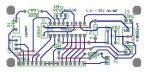
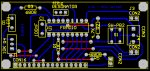
I have made up a PCB and populated the board. When I turn the power on the welcome message briefly shows before the segments half fill in a triangle shape with dots that make up the segment. (if that make sense). The LED also comes on and stays on.

The code I have tried is:
Code:
setfreq m4
high 0
pause 100

serout 0,N2400_4,(254,1) ' blank the screen
pause 30 ' short delay to enable blank to complete
serout 0,N2400_4,(254,128,"Top Line") ' top line message
serout 0,N2400_4,(254,192,"Bottom Line") ' bottom line message
pause 2000

Main: 'start a loop
let b1 = b1 + 1 ' increment variable
pause 500 ' short delay
serout 0,T2400_4,(254,192,"Count = ", #b1) ' output value on bottom line
goto main

--------------------------------------
AND THIS
--------------------------------------

setfreq m4
high 0
pause 100

main:
for b0 = 0 to 63 ‘ start a loop
read b0,b1 ‘ read value into b1
serout 0,N2400_4,(b1) ‘ transmit value to serial LCD
next b0 ‘ next loop
I have also tried to interchange the N and the T but no difference.
Can someone also tell me what the difference is between the N and the T.

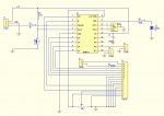
This is my circuit, I’m pretty sure it is correct, although another set of eyes checking it over wouldn’t hurt.


Thanks for any help that anyone can give me.
Mike
 

Attachments

russbow

Senior Member
Mike,

Have run this on an 18x perfectly after one small alteration to your code.

If you want to run

serout 0,N2400_4,(254,1)

then take out the HIGH 0 at the beginning. If you keep the HIGH 0 then you must run

serout 0,T2400_4,(254,1)

I think the T idles high so the pin must be high to start with.

One other point, and forum members will tell you it is a timing thing, I have found that glee bay displays, although the HD (?) standard need an extra 254,1 command in the clear screen

serout 0,N2400_4,(254,1,254,1)

Goes against the theory,but on my cheapos it is needed.

I'm afraid part two of your code needs a re-visit

Code:
--------------------------------------
AND THIS
--------------------------------------

setfreq m4
high 0
pause 100

main:
for b0 = 0 to 63 ‘ start a loop
read b0,b1 ‘ read value into b1
serout 0,N2400_4,(b1) ‘ transmit value to serial LCD
next b0 ‘ next loop
what's the value of b1? Does it change? Should the serout be #b1

Maybe worth looking at the way you initialised the display in the first part, and applying it to the second part.

Russ
 
Last edited:

zener

Member
Thanks for the quick reply Russ,

I tried your suggestion for the first part of the code, but still no luck. I did see that suggestion in a post earlier and tried it then but without taking out the high at the beginning.

For the 2nd part of my code that I tried I took it out of manual 2 page 174 (at the bottom of the serout command). I did try you suggestion for this code as well with no luck.

Thanks again.
Mike
 

russbow

Senior Member
Mike,

The jumper settings are significant and will expect particular code.

Jumper 1 When closed the power-up ‘welcome’ message is disabled.
Jumper 2 When closed the baud rate is set to 9600 (open value is 2400)
Jumper 3 When closed the serial protocol is inverted, for direct connection to a PC.
Jumper 4 When closed the LCD module is configured to use just one line instead of two
My test rig is permanently wired with the FRM chip leg 10 to 0v, and 11, 12 & 13 left open circuit.

I must therefore run at T2400. Your code runs fine on my rig, taking pin 0 high to start with.

Circuit looks good too, as long as there are no mistakes in building it.

Close the jumper on pin 10, and leave the others open.

Get you first bit of code working first, forget part two.

R.
 
Last edited:

zener

Member
Russ,

All jumpers were open, I have closed jumper 1 and as expected the welcome message now does not show when I turn the power on.

I ran the 1st part of the code with the changes but again still no luck. I checked the PCB very carefully following each track and I couldn't find anything wrong. (not to say that there is isn't - just couldn't pick anything up).

Any other suggestions

Mike
 

russbow

Senior Member
What Picaxe are you using Mike?

Does your prog pass syntax check?

This is your code that runs ok on my rig.
Code:
setfreq m4
high 0
pause 100

serout 0,t2400_4,(254,1) ' blank the screen
pause 30 ' short delay to enable blank to complete
serout 0,t2400_4,(254,128,"Top Line") ' top line message
serout 0,t2400_4,(254,192,"Bottom Line") ' bottom line message
pause 2000

Main: 'start a loop
let b1 = b1 + 1 ' increment variable
pause 500 ' short delay
serout 0,T2400_4,(254,192,"Count = ", #b1) ' output value on bottom line
goto main
maybe increase pause 30 to pause 100.

Can you post close up of pcb?

R.
 

zener

Member
I'm beginning to think that it my circuit.

I can't take a pic of the pcb board as it is now attached to the lcd but here is the pcb layout. Probably not the best layout (open to any constructive criticism).

I ran the code again copied straight from your post and changed the pause from 30 to 100, still nothing.

I'm using a picaxe 08m, the AXE021 and I'm also trying the code on a 28x2, the AXE200 module. Changing the output to B.7.

Well thanks for your help so far, off to bed I have an early start tomorrow.

Thanks again
Mike
 

Attachments

cactusface

Senior Member
Hi All,
I too have just ordered one of those LCD's from SureElectronics in China, but mine will be Blue/White I hope. I can agree with RussBow and say that my current LCD, also an eBay buy, does also require the extra clear screen command.
<quote>
One other point, and forum members will tell you it is a timing thing, I have found that glee bay displays, although the HD (?) standard need an extra 254,1 command in the clear screen serout 0,N2400_4,(254,1,254,1)
<quote> Glee bay, yes I like it, almost true..
Regards
Mel.
 

russbow

Senior Member
Had a look at your PCB and another look at the circuit diagram.

I may be missing it, but dont see the 10K resistor between the 1K serin and earth.
 

zener

Member
I didn't use the 10k resister because in the instructions it said it was not required for connection to the picaxe/basic stamp under

c) Serial Connection

maybe I should try it and see what happens??

Mike
 

Attachments

russbow

Senior Member
Tracing out your pcb is a little difficult as the pic is so small. I cannot find contiuity of the 0v line.

Pins 1 & 5 are commoned and connect to the VR, also pins 7,8,9,10, crystal, capacitor.

I cant see the connection between 5 & 7 . Time for the test meter?
 

zener

Member
Thank again for your reply Russ,

I am posting another shot of the PCB, hopefully it's a little bigger. I didn't realise the 1st one was so small.

I will have a closer look at the tracks you have mentioned.

Mike

I have checked the connection between 5 & 7, it has a link connecting them on the PCB that I am trying to get working. (for some reason it wasn't on the 1st attachment)
 

Attachments

Last edited:

russbow

Senior Member
Much better pic Mike.

All the earth commons seem OK, & the rest match the FRM data sheet.
So, should be OK providing it all rings out on the board.Do you get the LED pulsing on pin 17 when data is being sent.

Also silly comment, you do have the earth connections between the picaxe and the FRM board commoned don't you.
 

zener

Member
The LED stays on continuous, it does not flicker at all.

The earth connection comes through "CON3" and then tees off to pin 5 of the FRM chip and the gnd pins of "CON16 / LCD". Is this what you mean by commonded between the picaxe & the LCD?
 

Technical

Technical Support
Staff member
When I turn the power on the welcome message briefly shows before the segments half fill in a triangle shape with dots that make up the segment. (if that make sense). The LED also comes on and stays on.
Do you actually get the 'Serial LCD' welcome message. You seem to, and if so there is nothing fundamentally wrong with your PCB / FRM010 chip.

The 'arrow' characters and LED constantly on means that the serial input to the FRM010 is continuously in the wrong state (ie permanently high if the polarity jumper is low or vice versa).

So this is either a short circuit (solder bridge type error) on the board around the serial input track, or a fault in the wiring to the PICAXE board. What PICAXE board are you using?
 

Technical

Technical Support
Staff member
Just realised you are using the AXE021. Using output 0 is therefore not really a good idea, as you need to keep swapping the prog/run jumper on the AXE021 back and forth. You are doing this aren't you.... if not output 0 is not actually connected to your PCB and so the serial in is floating, hence the dodgy characters.
We would use a different output whilst testing.
 

zener

Member
Yes i am getting the lcd welcome message, very briefly before the lcd half fills with like a triangle in each segment.

Yes I'm using the axe021 and using output 0 (I have been swapping prog/run jumper) I have also tried output 1 without swapping the prog/run jumper.

I have also tried the PICAXE-28 Module (axe200) using the B.7 out.

Okay, my next step will be to remove the pcb from the lcd (it's too close) so I can check for short circuits and change the output 0 to 1 when programming.

Thanks so far, I will let you know how I go.
Mike
 

Technical

Technical Support
Staff member
A multimeter should quickly find a short circuit without disassembly - you are only looking at the serial in line

Just to double check, if you are using two separate power supplies for LCD/PICAXE the 0V between both power supplies is connected together (described as 'common earth' above). This is essential to match the logic levels of both systems.
 

zener

Member
It's working.

First of all I would like to thank Russ & Technical for helping over the last couple of days, suggesting things to try, I did feel a little lost knowing what to try next. If it was the code or my circuit, knowing that the code that Russ used worked then narrowed it down to my circuit.


In the end I unsoldered the con16 connector to seperate the pcb & lcd (they were 6mm apart). Then I followed the serial line through and found the problem, I then looked on the pcb drawing & could see the problem also.

I can see it so clearly now, there is a (red) link running vertically near the 1k resistor, this should have been a track. So there was affectively a break in the serial line. Once I fixed this everything worked as it should have.

So thank you once again.

Mike
 
Top