Fried PIC ? - Strange Behavior

Hydroid

Senior Member
I'm currently attempting to get a binary clock working on a Picaxe 28X1 using the AXE091 Development Board and a separate breadboard for additional space.

I'd being playing around with code for about two hours and uploaded at least a dozen program revs without issue. After another code adjustment, I hit the program button and got an error message; Chip missing, not powered or requires a reset (something like that). I ensured that the programming connector was inserted firmly (it was) and the board definitely had power, but it refused to accept programming. A computer reboot failed to solve the problem too.

As a test, I removed the 28X1 and installed another one. Viola, programming accepted. I figured I fried the first one somehow and just continued with the new one.

About 20 minutes later, program error message again ?? This time, the LED connected to the RTC clock pin 7 also stopped flashing and went solid. Many troubleshooting attempts and nothing.

Being brave (or some might say stupid) I installed my last 28X1 after thoroughly inspecting the boards and connections. Applied power, program cable and reset the RTC to valid values (there was some strange numbers in the registers) and all was OK again.

After dinner, I removed the 28X1 and installed the second one and to my surprise, its working again. Tried the first one, but nothing. It appears totally dead.

So, being a NOOB at these Picaxe chips, has this happened to anyone. I've been an electronics hobbyist for more than half my life and have never seen a chip come "back from the dead".

Any ideas ?

Regards, John.

BTW, I did manage to get the clock to work - small prize for a dead PIC... :(
 

BeanieBots

Moderator
As you are using the AXE090 board it is unlikley to be anything to do with the download circuit and/or reset lines, however, we do not know what you have on the PICAXE outputs.
I'm guessing that you have LEDs on the outputs?
Do they have series resistors?
Are you using the on-board regulator or powering direct?
What is your power source?

PICAXE (PIC) chips are VERY robust but over-voltage or excessive load on the outputs can destroy them.
The fact that it has happened to you several times is a very strong indicator that there is something wrong with what you are doing.
FULL details would be needed to determine the exact cause.
 

westaust55

Moderator
While the individual outputs of the PICAXE can handle up to 25mA Absolute maximum as can a typical non high-power LED (although an upper limit of 20mA is safer),
the total power consumption for the PIC16F886/7 microcontrollers is
From the PIC datasheet:
Maximum current sourced by all ports (combined)(2)............................................. 90 mA

This is an absolute rating and you should be drawing something less than this like 80mA total.

We do not know exactly how you are driving the LED’s of you binary clock, but presuming some level of multiplexing with hours, then minutes then seconds you could have say 5 LED’s energise at one time.

Allowing a few mA for the circuit and other parts of the circuit (such as i2c for the RTC) then you would be limited to 16mA per LED.

In reality you can have higher value series resistors and limit the LED current to something like 8 to 10mA and still see the LED’s quite easily.

But in the absence of full details, assuming no or inadequate current limiting for the LED’s then unfortunately YES, you may have let the puff of smoke escape from the PICAXE 28X1 which would then be assigned to the “round file”. :eek:
 

Dippy

Moderator
Hydroid, you are new to this, so just a gentle reminder that people need good info to be able to help. Sadly, we can't see over your shoulder and our Crystal Balls are clouding over because they were a cheap job-lot made by the Lo Hung Ball company bought from Ebay :)

So, if you want sensible/considered/valid replies you MUST include details of all the connections made in your question. Power supply details, jumper settings, I/O details, connections to external devices etc.

It's almost like me asking you; "My car won't start, why not?"

The previous posts have given you some important info and asked some pertinent questions.


So, post a neat schematic of your circuit and links to any unusual component Data Sheets where necessary.
A schematic of your connections as a diagram will save paragraphs of text and will, hopefully, get a quicker response.
Handwritten is fine if neat.

Then, people can suggest methods/tests to sort your problem.

Your first tests should have included:
Check the Voltage getting to the PICAXE + and - ic socket pins BEFORE inserting chip.
Check for short-circuits or shorted devices or wrong placement.
Checking PCB for errors or damage.
If all OK then insert PICAXE and measure the current when initially powered up.
Then, Programming and testing PICAXE with no peripherals connected.

And a tip for you and everyone;
SAVE UP your pocket money and get a Bench PSU with adjustable current limiter.
Goodness knows how much (money & time) I have saved over the years by having one of these. I use expensive HiQ ones, but there are many low cost good-enough versions around.
 

hippy

Ex-Staff (retired)
Another reason for apparently 'dead' PICAXE is the program waiting for input and ignoring the download requests; these then get reported as failed downloads, hardware not found.

The way round that is to do a hard reset. Either hold the Reset button until the download screen shows "Connecting to hardware..." or power off, leave for a while, then power on when that appears.

The most likely cause of permanent PICAXE failure is powering from too high a voltage, reverse voltage, and drawing too much current through the I/O pins. As others have said, full details of your circuit and program will help people assess if any of those have occured.
 

Hydroid

Senior Member
My Appologies

Sorry guys, I was actually only curious about the vulnerability to the PICAXE chips to static electricity. Previous to PICAXE, I've only dealt with Basic Stamps :)eek: I know) and I've never "popped" a chip due to static...

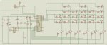
Anyway, I can understand where a diagram is worth a thousand words, so I've attached my circuit in .jpg format (I was going to attach my VSM .DSN file, but wasn't sure if people who aren't running VSM would be able to view it).

So to address some of the ideas offered:

- I'm using the AXE091 development board and powering everything from a 9V adapter connected to the boards input jack. The boards onboard 5V regulator then distributes 5V to the components.

- I have verified that the regulator's output is exactly 5.00 volts and the input to the 28X1 is 5.00V (across pins 20 & 8) - although strangely, there mere act of measuring this causes the PIC to stall (time display freezes). RESET DOESN'T get it working again, but setting the time DOES :confused:

- All components shown, except for the display LED's, their resistors and transistors, are on the AXE090 board. The display components are on a separate breadboard with jumper wires connecting to the AXE090 pins as required. The LED connected to the RTC pin 7 (D1 and R4) are on the AXE090 breadboard. I have that there so I can have it blinking at 1Hz as a verification that the RTC is working.

- I have confirmed that the connections match what's shown in the schematic (no shorts, loose wires...)

- I hadn't considered the mA loading on the output pins. I am using inline 300 ohm resistors on each LED in the multiplexed display. As a test, I measured the current from OUT0 (Pin 21) and never saw my DVM exceed 3mA. Since they're multiplexed, there's never more than one LED being fed from any of the 4 outputs (OUT0-OUT3). In the columns, the transistors switch the current, so the only current pins 11-13 and 16-18 supply is the base current (very low)

- I did try holding the RESET button on the board while programming (per the error message box) but that didn't work.

With the STAMP, it was recommended to ties all un-used inputs to ground to prevent them floating. I did a search on this forum and it seemed some do / some don't. Per the schematic, I'm not using outputs OUT4-7 (Pins 25-28) or inputs ADC2/3 (Pins 4-5). They're just floating; Would that matter ?

Incase it's required, here's the code:

Code:
# picaxe 28X1

#rem
-Binary clock using Picaxe 28X1 and DS1307 RTC. Based on code seen on project by user "kevrus" in the "audio/visual"
 section of the PICAXE user forum. Original code was for a 3 column clock using 17 LED's in a 5,6,6 layout. Code
 modified for use with 20 LED matrix in a 2,4,3,4,3,4 column layout.
-See Binary Clock 6 Column LED.DSN for schematic
#endrem


main:
setfreq m8						'sets operating frequency at power-on
i2cslave %11010000, i2cfast_8, i2cbyte			'initiates and sets DS1307 slave address
let dirsc=%11100111					'sets pins 0,1,2,5,6,7 on portc for ouputs

goto readtime

write_time:
if porta pin0=1 then write_time			     	'loops until button released			
writei2c 0, (b0, b1, b2)					'writes the 'set' hrs,mins,secs into ds1307

low portc 0						'turn off all transistors
low portc 1
low portc 2
low portc 5
low portc 6
low portc 7

readtime:

if porta pin0=1 then ten_hrs_set
readi2c 0, (b0, b1, b2)					'read secs,mins,hrs and store in variables


let pins=%00000000					'switches off all LEDs
low portc 7						'switches off 1's sec LEDs
high portc 0						'switches on 10's hr LEDs
let b4=b2/16						'extracts high 4 bits of b2 to b4 (10's hrs)
let pins=b4						'turns on 10's hr LEDs


let pins=%00000000					'switches off all LEDs
low portc 0						'switches off 10's hrs LEDs
high portc 1						'switches on 1's hr LEDs
let b5=b2 and %00001111					'extracts low 4 bits of b2 to b5 (1's hours)
let pins=b5						'turns on 1's hr LEDs

let pins=%00000000					'switches off all LEDs
low portc 1						'switches off 1's hrs LEDs
high portc 2						'switches on 10's min LEDs
let b6=b1/16						'extracts high 4 bits of b1 to b6 (10's min)
let pins=b6						'turns on 10's sec LEDs


let pins=%00000000					'switches off all LEDs
low portc 2						'switches off 10's min LEDs
high portc 5						'switches on 1's min LEDs
let b7=b1 and %00001111					'extracts low 4 bits of b1 to b7 (1's min)
let pins=b7						'turns on 1's min LEDs


let pins=%00000000					'switches off all LEDs
low portc 5						'switches off 1's min LEDs
high portc 6						'switches on 10's sec LEDs
let b8=b0/16						'extracts high 4 bits of b0 to b8 (10's sec)
let pins=b8						'turns on 10's sec LEDs


let pins=%00000000					'switches off all LEDs
low portc 6						'switches off 10's sec LEDs
high portc 7						'switches on 1's secs LEDs
let b9=b0 and %00001111					'extracts low 4 bits of b0 to b9 (1's sec)
let pins=b9						'turns on '1's sec LEDs


goto readtime


'Set 10's Hours:


ten_hrs_set:

if porta pin0=1 then ten_hrs_set				'loop until set button is released
low portc 1						'switches off other 5 columns
low portc 2
low portc 5
low portc 6
low portc 7
high portc 0						'switches on 10's hrs LEDs
b4=0							'resets b4 (10's hrs) to zero for setting

ten_hrs_inc:

if porta pin0=1 then one_hrs_set				'jump to routine for setting 1's hrs
if porta pin1=0 then ten_hrs_inc				'loop until inc button is pressed

ten_hrs_loop:

if porta pin0=1 then one_hrs_set				'jump to routine for setting 1's hrs
if porta pin1=1 then ten_hrs_loop				'loop until inc button is released
b4=b4+1 			 				'increment 1's hrs variable by 1
if b4>2 then let b4=0					'resets b4 to zero if >2
endif
let pins=b4						'display 10's hrs on leds in binary
if porta pin0=1 then ten_hrs_set				'jump to routine for setting the 10's hrs
pause 10
goto ten_hrs_inc


'Set 1's Hours:


one_hrs_set:

if porta pin0=1 then one_hrs_set				'loop until set button is released
low portc 0						'switches off other 5 columns
low portc 2
low portc 5
low portc 6
low portc 7
high portc 1						'switches on 10's hrs LEDs
b5=0							'resets b5 (10's hrs) to zero for setting

one_hrs_inc:

if porta pin0=1 then ten_min_set				'jump to routine for setting 10's min
if porta pin1=0 then one_hrs_inc				'loop until inc button is pressed

one_hrs_loop:

if porta pin0=1 then ten_min_set				'jump to routine for setting 10's min
if porta pin1=1 then one_hrs_loop				'loop until inc button is released
b5=b5+1 			 				'increment 1's hrs variable by 1
if b5>9 then let b5=0					'resets b5 to zero if >9
endif
let pins=b5						'display 1's hrs on leds in binary
let b3=b4*16						'Calculate 10's hrs as high 4 bits pre BCD hrs load
let b2=b3+b5						'Assemble 4 high and 4 low bits of hrs to b2 for RTC load
if porta pin0=1 then ten_min_set				'jump to routine for setting the 10's mins
pause 10
goto one_hrs_inc


'Set 10's Seconds:


ten_sec_set:

if porta pin0=1 then ten_sec_set				'loop until set button is released
low portc 0						'switches off other 5 columns
low portc 1
low portc 2
low portc 5
low portc 7
high portc 6						'switches on 10's sec LEDs
b8=0							'resets b8 (10's sec) to zero for setting

ten_sec_inc:

if porta pin0=1 then one_sec_set				'jump to routine for setting 1's min
if porta pin1=0 then ten_sec_inc				'loop until inc button is pressed

ten_sec_loop:

if porta pin0=1 then one_sec_set				'jump to routine for setting 1's min
if porta pin1=1 then ten_sec_loop				'loop until inc button is released
b8=b8+1 			 				'increment 10's sec variable by 1
if b8>5 then let b8=0					'resets b8 to zero if >5
endif
let pins=b8						'display 10's sec on leds in binary
if porta pin0=1 then one_sec_set				'jump to routine for setting the 1's sec
pause 10
goto ten_sec_inc


'Set 1's Seconds:


one_sec_set:

if porta pin0=1 then one_sec_set				'loop until set button is released
low portc 0						'switches off other 5 columns
low portc 1
low portc 2
low portc 5
low portc 6
high portc 7						'switches on 1's sec LEDs
b9=0							'resets b9 (1's sec) to zero for setting

one_sec_inc:

if porta pin0=1 then write_time				'jump to routine for writing time to RTC
if porta pin1=0 then one_sec_inc				'loop until inc button is pressed

one_sec_loop:

if porta pin0=1 then write_time				'jump to routine for writing time to RTC
if porta pin1=1 then one_sec_loop				'loop until inc button is released
b9=b9+1 			 				'increment 1's sec variable by 1
if b9>9 then let b9=0					'resets b9 to zero if >9
endif
let pins=b9						'display 1's sec on leds in binary
let b3=b8*16						'Calculate 10's sec as high 4 bits pre BCD sec load
let b0=b3+b9						'Assemble 4 high and 4 low bits of sec to b0 for RTC load
pause 10
goto one_sec_inc
I had to remove the "Set minutes" code to meet the 10,000 character limit, but it's the same as the "Set hours" with the variables adjusted accordingly.

Hopefully this now provides a complete picture.

Thanks for the help,

Regards, John.
 

Attachments

Last edited:

Andrew Cowan

Senior Member
It's because you have long comments in your code box - add a carriage return and it'll appear smaller.

PICAXEs are pretty resistant to static - I've never blown one.

A
 

lbenson

Senior Member
>because you have long comments in your code box

Particularly the first line in your "#rem". Edit the post to turn that into several lines, and all will be back to screen-width and we'll be able to read your post more easily.
 

Hydroid

Senior Member
Thanks

Thanks for the tips wrt the comments in the code box.

Fixed now, looks much better.

Put it down to another NOOB mistake :eek:

John.
 

Hydroid

Senior Member
PICAXEs are pretty resistant to static - I've never blown one.A
Good to know. Given that the scond one seems to have come back to life after appearing "popped", I'm not ready to give up and "round-file" it as was said earlier. Maybe I'll let it "rest" a little longer and see what happens ;)

John.
 

westaust55

Moderator
Sorry guys, I was actually only curious about the vulnerability to the PICAXE chips to static electricity. Previous to PICAXE, I've only dealt with Basic Stamps :)eek: I know) and I've never "popped" a chip due to static...
While there are diodes etc built into most IC’s these days to help prevent damage due to electrostatic discharges, electrostatic discharges may still cause some marginal damage to the chip which does not cause the chip to fail outright but can lead to some intermittent issue – particularly with the I/O which are the parts of the circuitry directly connected to the physical pins.

Over time the weakened part of the circuit can fail or just give occasional erroneous actions which leave you wondering what went wrong and blaming others parts of your project.

As an anlog circuit analogy, many years ago I had a 200 Watt HF radio amp where the antenna was struck by lightning. Result was virtually no output from the amp. Removed and bench tested the output transsitor with a few basic tests such as gain (Hfe) and the like. The transistor appeared to be okay so it was soldered back into the cicuit. Still only a few mW of output from the Amp.
Looked in the databook for the transistor to find that the “transistor” was in fact a pack which had a group of transistors in parallel. Turned out the lightning strike took out probably all but one of the transistors in the pack so the gain measured okay but there was no current capacity.

So in summary, after an over voltage condition (be it power supply or ESD), the IC circuitry will stressed and partial damage is highly likely. The chip may continue to function but may later fail or give intermittant erroneous results.
 

westaust55

Moderator
- I hadn't considered the mA loading on the output pins. I am using inline 300 ohm resistors on each LED in the multiplexed display. As a test, I measured the current from OUT0 (Pin 21) and never saw my DVM exceed 3mA. Since they're multiplexed, there's never more than one LED being fed from any of the 4 outputs (OUT0-OUT3). In the columns, the transistors switch the current, so the only current pins 11-13 and 16-18 supply is the base current (very low)
What you say is not correct. The code you have for the units LED’s in hours minutes and seconds can bring up to three LED’s on simultaneously: For example:
let b5=b2 and %00001111 'extracts low 4 bits of b2 to b5 (1's hours)
let pins=b5 'turns on 1's hr LEDs
units number of 7 = %00000111 ==> 3 LED’s on

With 5V supply and a red LED with around 1.2V forward volt drop and the 300 Ohm resistors you mention, during the on time, the total current will be around 12.6mA per LED so ~38mA total. and looks like an average of 3mA per LED when on for just 15% of the time . Still within the PIC chip capability but a point to be aware of.
 

Hydroid

Senior Member
What you say is not correct. The code you have for the units LED’s in hours minutes and seconds can bring up to three LED’s on simultaneously: For example:

units number of 7 = %00000111 ==> 3 LED’s on.
True for total current supplied by the PIC. I only meant that at no time is there ever more than one LED being fed from one of the OUT0, 1, 2 or 3 pins although all three LED currents are being sunk by the transistor...

Well, I don't know what to say. I posted my second message with schematic and code at 11:40 (my time). It's now 23:10 (11.5 hours later) and I've had the clock running on my desk since then. It has not failed once?

Thanks for all the ideas and help from all.

With your indulgence, I would like to ask one more question if I may.

In the code, the RTC is set using only the seconds, minutes and hours (first three varaibles). Is this OK, or should you always use the full 8 locations to also set day of the week, date, month, year and control ?

The reason I ask is that on page 8 of the Picaxe and the I2C bus file, which I downloaded from the Datasheets area, it states that to set the correct time after first power up, the current time must be written - and it gives the example of 11:59:00 on Thursday 25/12/03. The very next section on reading the RTC, shows an example where they just read the first 3 locations (s, m & h).

Each time I've had a crash, I've noticed that my RTC pin7 LED has gone solid, so something is affecting the control location.

Just curious,

Regards, John.
 

westaust55

Moderator
When you first energise the DS1307, as well as entering the time and possibly date, you MUST also set the control register otherwise the clock is not activated.(Many in the past have fallen foul of this fact).
If you have a battery back up (3V lithium) then the RTC will retain the time even when the PICAXE is off.

If you are using only the time, then I guess (untested by myself) that yes, you can set just those values but as you need to also set the control bit, you either must put some value into the date registers just to step across them, or use a second i2c comms write statement to set the control bit.
Suggest it is much neater to do it in one write statement – even if the data values are not current.
 

Hydroid

Senior Member
When you first energise the DS1307, as well as entering the time and possibly date, you MUST also set the control register otherwise the clock is not activated.(Many in the past have fallen foul of this fact). If you have a battery back up (3V lithium) then the RTC will retain the time even when the PICAXE is off.
I used a small bit of code to set all the values the first time and I have a 3V cell installed so it remembers.

It's now run almost 24 hrs without incident - although I've kept clear of it incase it is my static electricity ;)...

Just for kicks I think I'll modify the code to force it to write all 8 values to the RTC each time and see if that makes a difference.

Thanks again for your assistance.

Regards, John.
 

BeanieBots

Moderator
Just for kicks I think I'll modify the code to force it to write all 8 values to the RTC each time and see if that makes a difference.
Well, that's the fun way to do it.;)
The boring (but quicker & predictable) method would be to read the datasheet and see what each of the registers do with what value.
Westy has given some clues of what is REQUIRED for predictable operation.:)
 

Hydroid

Senior Member
The boring (but quicker & predictable) method would be to read the datasheet and see what each of the registers do with what value.
As my wife would attest to, I'm a typical male and we don't read manuals (or ask for directions) unless we can't get it to work with trial and error :D

Seriously, I did read that data sheet and have revised my code to write ALL values, up to and including the control, each time it performs a 12c write. As an added bonus, since the RTC now knows the time and date, I modified my layout (3 more LEDs) and code so that it can now display the time and with the press of a button, uses the same LEDs to display day of week, date, month and year.

It was the data sheet that explained why my month routine wasn't working. Figuring that there are only 12 months, I assumed (yes I know what happens when one assumes :eek:) that the lowest 4 bits of location 5 could hold the number 1-12. It was the sheet that showed it actually uses bit4 to hold the value for 'tens' of months...

Who knows, maybe these datasheets are useful after all ;)

Regards, John.

BTW, this morning I tried the Picaxe that refused to accept programming the other day and appeared fried.... It worked :confused:
 

westaust55

Moderator
As my wife would attest to, I'm a typical male and we don't read manuals (or ask for directions) unless we can't get it to work with trial and error :D

Telling of age, but . . .
Guess I grew up in a time well before the internet. When I lived on a small island in the 1970's (parts flown in from thousands of miles away) and had to get the datasheets by "snail" mail so it was imperative to read them thoroughly otherwise my electronics and computer related hobbies would have reached a demise many years ago.
 
Top