Failing MOSFETs

Goeytex

Senior Member
I did note the IGBT 1.5K internal gate resistor but was (still am) not clear how that related to the requirement of the external resistor you suggested or, if required, how to calculate its value.
The "requirement" I gave was suggested for a specific IGBT device. That requirement became null and void when a
different IGBT device was used instead. In that case all bets are off.

Like MOSFETS, not all IGBT's are the same and they don't all have the same drive requirements.
 

papaof2

Senior Member
Crap, spoke too soon. The IGBTs are now blowing on load power plug-in just like the MOSFETs. I wonder if this is related to the instantaneous 60 cycle line voltage at the time of contact (which may explain why the problem is intermittant).
Sounds as if your project might benefit from a zero-crossing detector to ensure the switching happens at the zero voltage/current point of the AC sine wave. If switching at the peak of the AC cycle, you could be exceeding the ratings of the devices you've tried.
 

NoSmoke

Member
papof2, yes, that's what I am suspecting - a zero-crossing detector might work but when/if this thing is ever connected to the wind mill, I would connect it only when o/p is low or zero so it may work fine in actual operation.

The 8,000uF filter cap I have across the rectifier also results in a big connect surge so maybe it's part of that particular problem. It will also put a start-up load on the mill to some degree which is detrimental (that's why I would like to avoid using it if possible).

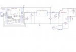
BTW, forgot to include the schematic in a previous post.

Picaxe PWM Schematic.jpg
 
Last edited:

inglewoodpete

Senior Member
Tell us more about the 8,000uF filter capacitor. What ripple current can it withstand? And remember that it will pack a lethal charge after the supply is disconnected!!

As an aside, it may pay you to have a resistor and diode in parallel to limit the charge current for the big capacitor without restricting the discharge rate.
 

Dippy

Moderator
Absolutely IP. I mentioned ripple earlier (post#13?) but I guess it wasn't read.
This must be a healthy capacitor. As IP says ; give us the spec.
The usual technique for big caps is 'pre-charge' and a suitable discharge resistor - all this can save you and the cap.

I really am confused by this latest incarnation.
A high gate resistor is going to result in slow switching which results in high switching losses. (usually=Bang!)
To reduce inductive loop effects you have the cap in close proximity to the switching device with some healthy, short tracks around the switching device.
The gate should be protected from large transients pos and neg.

This looks like unsuitable design spec. and I haven't any idea about the physical wiring which is also significant.
In MOSFET and IGBT power switching any stray inductances and even recovery times can cause big and fatal transients.
Once again, the design should be tight, fat and the designer should start at low voltages and should be making critical measurements at that stage - any nasties at (for example) 24V are going to be multiplied as you turn up the wick.
 

NoSmoke

Member
IP, all I know about the filter cap is it's 8,000uF, 175V, 200V surge, part number Mallory EAP802X175X5L3PH. I don't know what ripple current it can withstand - how does one determine that? I did use that particular cap only because it's what I happened to have on hand.

Good suggestion about the charge current limit - I will do that and try it once the new batch of IGBTs arrives.

I do appreciate the help given here without the condescention that sometimes seems to appear on this forum. Thank you.

Dippy, I pressume you are referring to this:

"A big fat suitable rated cap between the Drain and Gnd/0V closely placed may help, but be aware of ripple values."

Yes, I did actually read it and installed a big cap. The "be aware of ripple values" part was also read but I don't (didn't) know how to deal with it. Perhaps you can elaborate a bit.

The high gate resistor was recommeded by Goeytex for the particular IGBT he suggested I try. Since that was not available from Digikey, I went with another similar part and used the same resistor although, in a previous post, I attempted to ask how to calculate the proper value. In any case, I'm not sure how that relates to the IGBT blowing on power up when there is no switching going on. Should I be using a lower value?

It may well be an unsuitable design spec - I would not contest that for a moment. But that's why I'm here, trying to turn it into something that works. What "critical measuremts" at low voltages would you suggest I make?
 

NoSmoke

Member
If anyone is still following the thread, I think I've found the source of the IGBTs blowing. It was pointed out to me on another forum that incadescent lamps have a v low cold resistance. My circuit (in it's later "incarnation") worked at loads of under 300W but failed rapidly at 900. The resistance of the 900W setup turns out to be about 1 Ohm so, at 150V, that's a 150 A surge (exacerbated by the 8000uF filter cap). I then connected a 1200W heater (in place of the light bulbs) with a cold resistance of about 13 Ohms. Now it seems to work fine.
 
Top