external 4MHz crystal inaccurate timing

Janne

Senior Member
Hello!

I'm trying to build a simple temperature logger based on picaxe 28x1. The goal is to build a device, that once per minute reads the temperature on DS18B20, adds them to a temporary location. Then, once per day the average temperature during the day is calculated, and also a min / max temperature picked from the table, and stored into an external 24lc16b eeprom.

The reason i put the crystal in with the picaxe, is that i would like to use the settimer command to keep accurate time with the crystal. However, while testing the timing, i noticed it was off by almost 2%(time was running 2% too slow in the picaxe).. Now i started to think about possible reasons. First thing that came to my mind was the sertxd command, that i used to transfer the elapsed time back to computer.. Does sertxd cause the 28x1 to switch back to the internal timer, or does it work with the external crystal, because it's also 4MHz? Also, in the future when i will use the readtemp command, will it switch to internal 4MHz, when running on external 4MHz? The datasheets mention about switching to 4MHz while doing the temperature conversion, but will it always switch to internal, if the external frequency is also 4MHz?

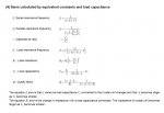
Another thing are the loading capasitors with the crystal.. I saw some site mention they should be something in between 10 - 47pF, I went with 10pF, since i had those plenty at hand. What exactly do the capasitors do in the circuit, and are they related to the oscillating frequency?

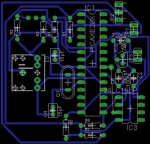
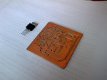
below is the code i used for testing, and a picture of the pcb, and layout.

Code:
#picaxe28x1

init:

setfreq em4
settimer t1s_4


main:

toggle 7
pause 500
toggle 7
pause 500

let W0 = timer
sertxd ("seconds elapsed ", #W0  , " _")

goto main
 

Attachments

hippy

Ex-Staff (retired)
I tested the following code on a 28X1 with external 8MHz resonator ...

Code:
#Picaxe 28X1
#Terminal 9600
#No_Table
#No_Data

SetFreq EM8
SetTimer T1S_8

Do
  If timer <> w0 Then
    SerTxd( #timer, CR, LF )
    w0 = timer
  End If
Loop
That seemed to keep accurate time, certainly not showing any error of the magnitude you are seeing. I timed a count of 100 intervals which took 99.97 seconds which is pretty bang-on given button push lag and neither me nor the stopwatch are calibrated.

On internal oscillator, 8MHz 3V3 21'C, that took 100.19 seconds, 4MHz 3V3 21'C took 100.25 which are comparable and again pretty close to expected.

I couldn't see any cap ratings in the 16F886 datasheet for crystal oscillators after a brief scan but 10pF may be too low, especially with +/-10% tolerance. Easiest solution is to use three-pin resonators with in-built capacitors.

I expect the switch for DS18B20 reading is to the internal clock regardless of already using external 4MHz but Technical will have to confirm that. I wouldn't expect any drastic loss of timer accuracy though. SERTXD doesn't switch the clock, baud rate depends on what the operating frequency is.

Even with the accuracy of a crystal there will still be some drift, hopefully that averages out but it probably accumulates.

You will probably need to re-think your sampling and averaging algorithm; a word variable cannot exceed a value of 65535 and with 86,400 seconds per day you will have to deal with overflow.
 

Dippy

Moderator
For your 'average' HC49 style crystal it is usually given as 18pF to 22pF.
Some specialist crystals have different values. Example: a Kyocera ZXC49 (smd HC49) is quoted as 12pF. And some of their tiddlers are around 8pF.

I can't explain the nitty-gritty (and can't be bothered to Google), but simplest to check manufacturer's Data Sheet as they ought to know best.

This, below, is from a Kyocera crystal Data Sheet. I've never read it.
 

Attachments

Technical

Technical Support
Staff member
Does sertxd cause the 28x1 to switch back to the internal timer,
No, but the timer (and all other interrupt based functions) are temporarily disabled during the sertxd command to prevent serial timing corruption.

Hence whilst the serxtd text is being sent the timer is not 'ticking' - hence your timing difference.

Have a look at the 'conflicts' appendix in part 2 of the manual for more details.
 

Janne

Senior Member
Thanks for all the help. I did try to google for the datasheet of the crystal, but I suppose because it's of some real old stock(unused still) I couldn't find any.

As for the sampling / averaging, I though I would use mayby 2 hour intervals, and calculate the average from it, and also picking min / max temperature. Then, at the end of the day i would average those 2hr time slices, and pick min / max values from all of those..2 hours would fit in nicely into the scratchpad. This part is still under thought thou :)

As to the Technical's post, I wasn't avare of the ticker being interrupt driven - i only though the timer variable overflow would have caused the interrupt being generated. One more question.. Is the interrupt generated each time the timer variable is increased, or on each tick? As, if it only interrupts on timer variable increment I could work around it by increasing the preset time to say 3 seconds, so I would have plenty of time to read the temperature if I time it just right after the timer is incremented.

If not, then I think I'll be better off just getting a DS1307.. Just what i was trying to avoid, don't have any at hand right now :)
 
Last edited:

Janne

Senior Member
Okay never mind that last question, i put another test running through the night, that avoided sending serial data during the incrementing of the timer value, but also this time the timing was off.. This time only though 1,3%, but still way too much.

So it's back to the drawing board now, or to order the ds1307 chip.

Code:
#picaxe28x1
#no_table
#no_data

init:

setfreq em4
settimer t1s_4


main:

pause 100

if timer <> w0 then 
gosub txd
endif

goto main

txd:

toggle 7
let w0 = timer
sertxd ("this is second number", #w0 , " ")

return
 

Janne

Senior Member
Okay I ran another 4 set of timing tests. This time, for the first hour I avoided using any commands that would interrup the timer ticking. For the second hour, I used the readtemp command every minute. The "unloaded" tests all were running 1.2s-1.8s too slow per hour, and with the read temp command each hour received a pretty constant 25% additional delay to the drift..
So now I think, that if I pick a value of 1.5s from the middle of the error range, and add the 25% to that to compensate, it would work in my application. In the worst case scenario, with 0.4s of cumulative error coming each hour, it would still only drift about 1 hour in a year span, which would be acceptable.

Next thing to do is to figure out the rest of the program.. i will post how this turns out in the long run. Below is the code I used for this test. For logging the error, i used a serial port terminal with timestamps turned on, to record the exact time of the serial messages.

Code:
#picaxe 28x1
#no_table
#no_data

symbol seconds = b3
symbol minutes = b4

init:

sertxd ("start of the test")
setfreq em4
settimer 34286 'setup the timer with 2 second preload

main:

if w0 <> timer then

	inc seconds
	let w0 = timer
	toggle 7
	if seconds > 29 then
		
		let seconds = 0
		inc minutes
	      if minutes = 60 then 
	           	sertxd (" 1st hour of the test passed")
	      endif
	      if minutes >60 then
	      	readtemp 7,b5
	     	endif	
	     	
	     	if minutes >= 120 then
	     		sertxd (" second hour passed, temp is", #b5)
	     	endif
	      	
	endif
endif

goto main
 

tiscando

Senior Member
timer t1s_4 discreptancy!

Hi,
I have just found a widespread discreptancy with t1s_4 being 49910.
This is where I think this has started:
The internal timer part of the settimer command reference manual pages say:
"Finally 65536 - 15625 = 49910, so our preload value become 49910."
All I could say about this calculation is that either 65536 should be 65535, or 49910 should be 49911.

Should it be 65536?
- If the preload value is 65535, then every time a minor tick occurs, the minor register overflows to 0, the timer wordvariable gets incremented (major tick), and the minor register gets preloaded with 65535 again. Thus, there is 1 minor tick per major tick, so 65536 - 65535 = 1.
- I calculated 34286 and 3036 using 65536, and I get the result of the major tick period being correct for their purpose for both of them.

So yes: where it is 49910, should be 49911.

However, I see 49910 everywhere, and I even simulated
w0=t1s_4
And I get the value 49910, not 49911, in w0 in the variables panel.

This means Janne, the timer is running 0.2304s slower per hour. Try replacing "t1s_4" with "49911" and see if you get better results

I calculated 49910 using 65536, and I got the major tick period being 1.000064sec.
 

tiscando

Senior Member
Another solution infact: try shortening the sertxd data comments. Didn't see that you're using 34286 instead of 49910 or 49911.
 

hippy

Ex-Staff (retired)
One thing that has not been considered is how is timing being measured ? How accurate is the device being used for that - that is, how do you know that an unloaded PICAXE's timing is not spot-on and the meauring device is not running fast ?
 

Janne

Senior Member
Hello and thanks for the comments.

I measured the "real" time it takes for the program to run with a serial port terminal on the computer - with the timestamps turned on.. so i could check the timing from the 3 hour messages on the test. I used a software package called "com port toolkit v3.9" for the job.

Anyways, I got the timing to work with reasonable accuracy by swapping the preload to 34301.. It still has some error, but the error doesn't seem to be cumulative, nor too serious. I'm now working on the main measuring and logging part on the logger.
 

hippy

Ex-Staff (retired)
PC clocks are notorious for being inaccurate and gaining or losing time. The situation is complicated by there being two clocks, a hardware clock controlled by a watch crystal and a software clock controlled by software ticks, set at boot from the hardware clock, then used by the OS whilst running.

Losing time is quite common, and I've had the clock visibly freeze while Windows was waiting for some things to happen ( not servicing interrupts which tick the time along is my guess ), but it seems gaining time is also a problem when one looks at the numerous posts on Google.

It is quite possible that the PICAXE is more accurate than your PC and the error you are seeing is the PC gaining time rather than PICAXE losing it ( when not doing anything which could lose time ), reality is likely to be some combination of each.

Measuring small errors over long times is very hard to do manually, even with a stop watch there's reaction time in pushing the button, and you don't know how accurate your stop watch is. Even so, I'd trust a stopwatch or wristwatch more than a PC for timing.
 

Janne

Senior Member
Thanks hippy for the insight.

I was not really aware that pc clocks were that bad.. That might explain why my results varied about + / - 1 sec per hour(i blamed picaxe for this :) ) even with the picaxe running on the external crystal.

I think, that once i have the rest of the logger set up, i'll add a simple led indicator to indicate changing of the hour.. i can then compare the timekeeping to a reliable source, like the time signal from the radio, or even GPS time. If need be, i can then adjust the timing on the picaxe.
 

MartinM57

Moderator
like the time signal from the radio
Not guaranteed either - ever had 2 radios on in the house ... old-fashioned FM and new-fangled DAB? The Radio 4 pips are several seconds behind on the DAB and you've no idea how far the FM ones are away from the real ones (UK situation at least)

or even GPS time
Probably the most reasonable bet these days, depending on how your receiver deals with it.


Something so simple as finding the time RIGHT NOW is actually quite hard...
 

slurp

Senior Member
Not guaranteed either - ever had 2 radios on in the house ... old-fashioned FM and new-fangled DAB? The Radio 4 pips are several seconds behind on the DAB and you've no idea how far the FM ones are away from the real ones (UK situation at least)
"A man with a watch knows the time; a man with two watches is never sure."

;)


regards,
colin
 

hippy

Ex-Staff (retired)
MSF "Rugby" radio timecode is an alternative to GPS but you'll still be limited to +/-1 second accuracy. Not sure what the equivalent to MSF is in Finland.

The best way is to have a signal which gates a high speed clock into a counter. That could be done using a PICAXE with crystal and a bit of external hardware, clock can come from PWMOUT.

http://www.picaxeforum.co.uk/showthread.php?t=12769

You could drive/pulse a relay instead of a LED and have that control a stopwatch or kitchen timer. Powering an analogue clock module would also have possibilities.
 

hippy

Ex-Staff (retired)
MSF only needs to provide 'spot-on' synchronisation then the local equipment can fill in the gaps as best it can. MSF only transmits one bit of information per second, and it takes a full minute to determine the time.
 

MartinM57

Moderator
Completely understand all of that - but you seem to explicitly state the MSF signal as having "+/-1 second accuracy" which seems very misleading.

http://www.npl.co.uk/upload/pdf/MSF_Time_Date_Code.pdf says quite clearly that the marker (carrier going to "off") transmitted every second is accurate to within +/-1 millesecond of UTC.

So the local equipment could keep accuracy to +/- 1 millisecond of UTC every second if it wishes with no internal clock at all (provided the signal was always transmitted - which it isn't). It could, of course, not know the actual time unitil it decodes the data stream in the signal...
 
Top