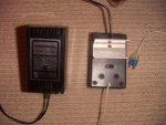
Erm, voltage regulator exploded

moxhamj

New Member
Re Evan "Until the input capacitor fails short." I'm not sure I understand.

The input capacitor should not short. Unless it was a faulty component, in which case, yes it could short, but so could every other component and 10,000V could come out of the power point etc etc.

Faulty components happen occasionally, but I suspect it is far more likely a component is being used out of spec (eg a 10V cap on 26V), or a component is the wrong way round.

Occasionally I've been stuck with 26V and anything over 20V, I use a pre-regulator - eg a 7815, and then the 7805. It shares the heat output. But it is also a fudge and not something you design in as it is wasteful of power.

I'd start simple. 9V wallwart. 5V reg. Caps as per the reg datasheet. Torch globe or resistor for current limiting. Red wires for +ve, black for -ve and other colours for the circuit. Leave the picaxe unconnected and test for 5V at the output of the reg.
 
Last edited:

evanh

Senior Member
Heh, doesn't really matter whether it's because of crap on the mains or fault condition or wrongly chosen/wired components or a faulty component, the result is the same. If there is substantial reverse current through the regulator then it will fail itself and pump the unregulated supply straight through.

That's why I like the zenor trick. It covers this situation as well as others.

@Evan,
Don't see how you would get low Z AC resulting from a shorted cap. Please explain.
The cap was in the process of failing to destruction, during this phase you'd prolly be able to measure it at an ohm or two. So, it's no longer performing it's smoothing/storage function but instead is dragging the transformer into saturation and stressing the rectifier to boot.

If one removes the input cap then the unsmoothed DC will still be regulated no problem. But with the low Z cap in place the regulator will charge the output cap on the rising slope and be forced to discharge it again on the falling slope.


Evan
 

moxhamj

New Member
Post #10 the cap was 10V but had 26V on it. It would be not surprising at all that it blew up. But there was a post earlier than that where we heard that the reg was a 26V supply.

It depends what sort of supply. If it was a nice smooth 26V regulated DC bench power supply, then the cap exploding should not upset the reg.

But if that supply was a transformer and bridge rectifier, and the cap blows up, you might be getting AC and that could be 1.4x the DC volts and maybe that is starting to push the limits of the 5V reg.

But blowing up a cap by putting more volts than it is rated for is something all of us does once. Keep those safety glasses on, and best not to mention tantalum capacitors. It also makes me think of other wiring shorts etc, especially as I'm still not 100% sure of the wiring diagram even after studying the photos.

I agree with evanh - zeners definitely have a place. I got a whole pile of 5V ones once at a good price, and I just chain them up in series to drop however many volts I need. Eg I had 36V DC and I wanted 5V DC, so I used 4 of those 5V zeners to drop 20V before the reg.

Addit: Tantalum capacitors. Sorry I mentioned them. They don't exist any more. You can't get them. Especially the low voltage ones with no indication of which leg is positive. No-one here has ever heard of them. Forget I ever mentioned them.
 
Last edited:

Dippy

Moderator
Blimey, this going circular and dragging on a bit isn't it?

B.E. said it was a 10V cap on a 26V DC supply.

Quote POST NUMBER 1: "i was using a 26v DC supply, rated for 1.5A". AC? Wheres that then - unless the PSU has gone splat.

Safety glasses? A pair of normal glasses to read the writing is more in order :)

Zeners have a place for sure. But if you don't have current limiting or a fuse then a piddly watt Zener will pop before a butch 7805 will.

RT(F)DS and RT(F)Component Spec is usually a good start.

I don't mean to sound like a Sm/Ass but I'm just about to: when I do prototyping I check every discrete with a multimeter prior to insertion into breadboard and on the first PCBs too. I double check ratings and polarity.

For significant current (esp. in a small enclosure) it is very unsuitable to drop such a voltage with a single linear regulator.

But the lesson is surely learnt and i honestly can't understand what all the postamble is for??

Tantalum capacitors.. "don't exist anymore" ?? Eh? You'd better get Farnell to tear 10 pages of their paper catalogue out then ;)
 

moxhamj

New Member
All good points Dippy.

The postamble is here because in the last post by Blue Eagle, he/she was going off to use batteries. I'm sure Stan would approve, but it seems a bit of a pity because regulated 5V supplies are not that complicated. I'd like to help get it working because my very first project when I was 14 was a 5V regulated supply, in a box, and I was very grateful for the help I got on that project (from my school, parents and a local electronics shop) because I had absolutely no idea what I was doing!

Oh, yea, plus when people blow things up, I'm the one that has to fish the bits out of their eye. And some can embed quite deep!

Electronics shouldn't be about things blowing up - in spite of the fact that some of my friends at school liked blowing up tantalums, I've actually never had a component explode. It could really put one off electronics. I'm still going to stick with recommending a small 9V (max 1A) wall wart and a 5V reg and a light globe to limit short circuit currents. Stick it in a small box, and you will still be using it in 25 years time.

Attached - my first electronics project. A 5V reg with a reverse switch so I wouldn't need batteries to run my lego.
 

Attachments

Last edited:

BeanieBots

Moderator
Good point about zeners Dippy. Typical max dissipation is 1/2W. At 5v they would pop soon after 100mA. Transorbs are similar but can take many 10's sometimes 100's of amps for uS durations. Have their purpose but NOT very good as crowbar 'safety' devices.

@Evanh, can't see that AC scenario ever happening in reality but not worth arguing over.

Tantilums:- electronics wouldn't be as much fun without them:)
 

evanh

Senior Member
Good point about zeners Dippy. Typical max dissipation is 1/2W. At 5v they would pop soon after 100mA. Transorbs are similar but can take many 10's sometimes 100's of amps for uS durations. Have their purpose but NOT very good as crowbar 'safety' devices.
Well, I count tranzorbs as the same thing. I've been known to use either. But the point was that upon failure a zenor goes short circuit. And I can assure you they can hack a lot of current before exploding. That said, I've seen tranzorbs split in two also, so it's not a perfect guarantee of over voltage protection.

@Evanh, can't see that AC scenario ever happening in reality but not worth arguing over.
Spoilsport. :p I thought I did a good job. I was specifically talking about this particular failure that Blue Eagle had. But storage capacitors do still fail short-circuit in the wild also.


Evan
 

evanh

Senior Member
Varistors are more amusing. They are even tougher, to the point where their legs are the weak point. :O But they aren't as precise.
 

evanh

Senior Member
That reminds me. Crowbarring with SCRs is not a done thing any longer. It was all the rage in the 1980's. Maybe it wasn't fast enough.


Evan
 
Last edited:

Dippy

Moderator
Just remember: Nothing can protect a circuit 100% - especially when a buffoon is involved.
(No implications intended. Confucius said this so don't blame me!)

I hear and I forget. I see and I remember. I do and I understand.

"Crowbarring is not a done thing any longer."
- really?
 
Last edited:

BeanieBots

Moderator
I was never a fan of crowbaring even in the 80's. However, in those days, one of the most common distributed power schemes was to have a high voltage bus (48v typ) with switching buck regulators. The common failure mode of the buck converter was SC on the main drive tranny. The crowbar would then (VERY quickly) pop an inline fuse. Modern SMS controllers have so many 'safety' features these days that crowbars are no longer needed.
Varistors are today's trendy crowbars.

A failed short Cap, won't have much AC across it. By definition!

"I hear and I forget. I see and I remember. I do and I understand.
"
Good to know you understood that it was that blinding flash that took out your eyesight. Shame you can't remember the spectacular bang that came with it. I fully empathise though.
 
All good points Dippy.


Oh, yea, plus when people blow things up, I'm the one that has to fish the bits out of their eye. And some can embed quite deep!

Electronics shouldn't be about things blowing up - in spite of the fact that some of my friends at school liked blowing up tantalums, I've actually never had a component explode. It could really put one off electronics. I'm still going to stick with recommending a small 9V (max 1A) wall wart and a 5V reg and a light globe to limit short circuit currents. Stick it in a small box, and you will still be using it in 25 years time.

Attached - my first electronics project. A 5V reg with a reverse switch so I wouldn't need batteries to run my lego.
Yep, it's actually the first thing that has blow up on me as well (though you are much more experienced lol)

Anyway, I swaped the 10v cap, for two 16v cap's and kept the LED with a 10k and the Vreg works fine on a 9v PP3 battery. Tried it with a multi-meter, nice 5.05v, no explosions or excessive heating.
 

Dippy

Moderator
Thats cool haha.
And i take it you may be looking at a different rated cap when you bung 26V DC on it?
Please say yes.
 

Andrew Cowan

Senior Member
I had a friend who plugged a 110V battery charger into a 240V source. It had a 240V varistor across the input (after a fuse). Shorting 240V through a comonent rated for 1/2W is not a pretty sight.

Andrew
 
Thats cool haha.
And i take it you may be looking at a different rated cap when you bung 26V DC on it?
Please say yes.
Erm? in the future, of course lol. not going to use that supply now though.

Also, after the sucessfull test with the led i hooked it up to the rest of the circuit and unfortunatly it got very hot again, and the battery got warm as well, suggesting a large current was drawn. So there is probably a short some where (cant for the life of me see it, and the multimeter still reports '500' when set to 2000k Ohm, so it's not really a direct short, bit confused there :S) Well anyway, i go back to school in a week and hopefully then i'll get a chance to get it sorted. Looks like it could take some time though.
 

Dippy

Moderator
It may be a semiconductor thing. Try pulling out the chips and that transistor(?) one at a time a repowering briefly with a multimeter set to current on the supply. 10 Amp setting, not 200mA as you'll pop the mm fuse.
Or you could try Dr-Acs light-bulb limiter.
 

BCJKiwi

Senior Member
Don't recall seeing an actual circuit diagram for this project yet. Gave up on the Pics as a bit hard to follow.

A circuit diagram and a fresh picture with some coloured wires would help us to help you further.

How many of those LEDS are lighting up at once? There doesn't seem to any current limit Rs on any of the segments - could easily draw significant current with many segments on at once!
 

evanh

Senior Member
run the wallwart 9V into a 5V reg, and put a 6V 500mA torch globe in series with the 5V output. If you short it, the worst that will happen is the globe lights up.
I dont quite get the setup your describing :confused:
The light bulb is in series with the supply and provides a current limit and a good indicator of current draw also. Foolproof even. :)

Those that want to spend some money on the setup can use a bench-top power supply instead. These have settable voltage and current.


Evan
 

moxhamj

New Member
Here we go:

Looks simple but it is a bit cunning. A light bulb has almost zero resistance when it is cold. When a certain amount of current goes through it, it heats up, and as it heats up, the resistance goes up. As the resistance goes up, it limits the current flow.

Most torch globes are 500mA. If you draw picaxe sorts of currents, eg 20mA, the torch won't light up at all and it will be as if it isn't even there.

If you short it, the bulb lights up, and you avoid zapping any components.

It works fine for batteries too.
 

Attachments

Last edited:

premelec

Senior Member
Yep, I like the series light bulb and also have been using PTCs [a solid state slow blow fuse type thermistor] which reset when they cool down again... also instantaneous circuit breakers which are a nuisance when you first try to charge a capacitor and they trip but save your bacon fast in case of other failure.

Also you can wire a 3 terminal LM317 as a constant current circuit with a single resistor - see data sheet - thus limiting input current on fault - within reason and with heat sink on LM317 etc...

Should be a separate forum on power supplies... :) Watts up?
 
First off, have a quick look at this thread:

http://www.picaxeforum.co.uk/showthread.php?t=8940&highlight=light+bulb+fuse

Then a BIG look at this site:

http://www.kpsec.freeuk.com/

and perhaps start with :
http://www.kpsec.freeuk.com/study.htm

e.
Ok, no offence but that second site is rather basic, 555's?
And I don’t fancy using a USB port when I am drawing excess current, and the final thing could easily draw 500mA or more so that not really suitable.

Attached is the circuit diagram. I have excluded the extra high-brightness LED's and LDR, as they are not in the breadboard atm and not really necessary.

Here's a quick explanation of what’s going on: On the picaxe, Pins 21 and 23 are the hour and minute clock pins respectively. Pins 22 and 24 are the hour and minute resets, respectively. Pin26 controls whether the displays are on or off (by giving them ground, when required. And yes, the transistor is rated up to 2A) Pin 25 operates a buzzer, for the alarm function.
On the 4026B, Pin 1 is the clock input, 1 high/low transition here increments the displays 1. Pin 15 is the reset. Pin 5 is the carry out, giving 1 pulse for every 10 on Pin 1, so if a 12 is required, twelve ‘pulsout’ commands are given and the first display counts to 9, comes back round to 0, and then up to 2, while the second receives 1 pulse.
The DS1307 RTC communicates with the PICAXE via the i2c bus, on pins 6 and 5, connecting to pins 14 and 15 on the picaxe. Pin 7 oscillates between high and low at a frequency of 1Hz, causing the two 3mm led’s to flash.

Anyway, that’s the theory!
 

Attachments

Dippy

Moderator
Or perhaps a 2 page summary sheet showing examples.
If Dr_Ac wrote it then call it "Watts Up Doc".
Mind you , that sounds like a painful experience.
And with friends like that, who needs enemas?

Blue Eagle: Have you actually TRIED pulling out a chip at a time and powering-up briefly so you can get a 'handle' on roughly WHERE the fault may lie.
You could start by simply powering up the PICAXE breadboard.
There is a LOT for YOU to do.
Help US to Help YOU.
 
Last edited:

evanh

Senior Member
Pin26 controls whether the displays are on or off (by giving them ground, when required. And yes, the transistor is rated up to 2A)
Looking good. Only error I noticed is the Emitter(Arrow head) of Q3 is on the wrong side. It should be connected to the power resistors rather than GND, the same way as Q2. Comparing your actual bread-board wiring with the ZTX751 datasheet I see you have it correctly oriented. :)

The board also has an extra resistor on Q3's base that is not in the schematic. Can't have out-of-date drawings now ... :p


Evan
 

evanh

Senior Member
Oh, and do label the transistors in the schematic. I had to do some digging to find out what you had used.
 

eclectic

Moderator
From post #66.

"Ok, no offence but that second site is rather basic..."

Yes. Absolutely. That's why I mentioned it!

It might help others avoid:

exploding regulators
exploding capacitors
describing legs as pins

and ......

You've been given lots of excellent advice in this thread.
I hope you've read and accepted it.

Best of luck for your future.
 

evanh

Senior Member
describing legs as pins
Or calling an I/O bit a pin! A leg *is* called a pin in electronics. The Picaxe is very confusing in this area. It should have been something more defined and extendable, Eg: outb, outb0, outb1, ..., ina, ina0, ina1, ...

The letters a,b,c, etc represent an 8 bit port and the digit represents the bit position within that port. What's more each symbol should only refer to one location. So there would be none of this input and output that go to two different set of pins but use identical symbols.


Evan
 

evanh

Senior Member
Or, the other way to do it would be to use the real pin numbers in the programs. This might be something that could actually be easily changed to.

EDIT: Sorry, wrong place for this rant.
 
Last edited:

manuka

Senior Member
I've been party to more blown up electrolytics (for educational purposes you'll understand) than a normal human has a right to, & in my experiences cap. over voltage failures are fizzers compared with the fireworks from reversed polarities. We've had some of the latter go off like rifle shots! Hence check that you had that electro. correctly polarised.

A lot of my recent work has been with 24 & 48V off grid systems,but for general electronics circuitry 5V is now pretty much THE standard. Although their switched mode output may be noisy, the numerous 5V "USB" plug paks now abounding,& capable of delivering ~1A, are really all one needs when mains supplied. Good old CHEAP 3 x AA C-Zn cells are so obvious a PICAXE supply that I ponder why any initial trails would look at anything else. These last ages- some at hand here are 4 yo. & still drive an 08M nicely. Stan

(To respect Dippy's sensitivities I've thoughtfully not attached my usual battery box picture).
 

Dippy

Moderator
aaaww.. I'm going to miss them ;)
A nice NEW photo would be nice though Stan. A well posed battery pack with neat wires - you know, a photo that FHM would be proud of.

Seriously though, the USB 5V packs are a great idea. If a bit noisy then add a few uH and a little ceramic. Good idea. And they're cheap as chips - even from non-Ebay sources... places where they might have a good warantee and next-day delivery, and where "CE" is genuine....
 

moxhamj

New Member
Re the circuit on post 66, R1 and R2 are not correct. You have them wired up as a voltage divider and the download circuit is not a voltage divider.

Re 555's being "a bit basic", don't be so sure!

Quick, without looking it up, what value resistors (or ratio of resistors) do you use on a 555 astable to get a square wave output with a roughly equal mark/space ratio? Not a totally academic question, because just this afternoon I needed a simple 1Hz square wave.

Also, maybe stick a 0.1uF across the power supply pins.

And be nice to Q2 and Q3 and put current limiting resistors on their bases. I use 2k7 but you could use anything from 1k to 10k. 330R on Q1 might be a little low. Transistors without current limiting resistors tend to get hot and draw lots of current. Hmm, that is one of the symptoms you are getting.

And C1 and C2 - when you write the value of a capacitor, write next to it the voltage rating. See my schematic a couple of posts above. It helps remind you what cap to use. You can use a 50V cap on a 5V circuit, but not a 5V cap on a 50V circuit. Writing the voltage rating reminds one not to grab the first cap that comes out of the junk box!

I'm not sure how your input switches work. When the switch is not pressed the input is floating and could give a random input. The usual way to do it is 5V=>resistor=>switch=>ground - then send the input to the picaxe from the point where the resistor joins the switch.

And just to add to evan's comment about Q3 - you have the wrong sort of transistor there. You have specified a PNP transistor (arrow going into the transistor) and you want an NPN. NPN transistors have the arrow going out of the transistor. Drawing it upside down doesn't fix the problem!

Actually, munching on my toast as I write this makes me think some of those transistors might be toast. No current limiting on the base, round the wrong way and the wrong transistor. They might be dead shorts by now, and that could be why the reg is blowing up. Can you pull the transistors and test them with a simple circuit - 2 resistors, a led and a 5V supply? Sing out if you need a simple transistor testing circuit.

By hook or by crook, we will get this working, even if it means digging embedded capacitor cases out of the ceiling!

And you had better duck, because some of the ones that manuka sent into orbit are going to be re-entering soon.

Dippy "and where "CE" is genuine...." Isn't it always genuine because it stands for "Chinese Electronics", doesn't it? *grin*
 
Last edited:

Dippy

Moderator
I think 555s are really useful, though a 50% duty from a 555 is a trciky one. No, I haven't looked it up, but from memory (honest), the equation says never unless you invert. Probably wrong.
For greater 'usefulness' and overall performance I moved to things like a CD4098, lot more legs (aka pins) but a lot more flexible.

PS. An easy test to see if the transistor is toast is to pull it out. I know its tricky ;)
 
Last edited:

moxhamj

New Member
I'll post the 555 answer in a bit...

Another point re the circuit, is Q3 needed for the moment and are the current limiting resistors needed? http://pandorasbox.50webs.com/projects/lesson04/decade counter.pdf

I'm not an expert on the 4026, but it might be easier to get it working without a blanking transistor first. Then add the transistor. But my gut feeling is that you don't need a current limiting resistor going into the collector, but you do need one for the base. And it should be possible to use one transistor with one base resistor to blank all 4 displays.

It also might be easier to redraw the schematic with some changes before plugging any more components in. We would all be more than happy to check a schematic and suggest changes. It will be quicker and cheaper than plugging in more components and having them blow up. Plus I don't want to have to dodge fallout from manuka and Blue Eagle.

Dippy - see the edited post #75 coz I worked out what CE means. I'm still pondering the first bit of post #67. I am wondering if I might be the butt of these jokes?!
 
Last edited:

Dippy

Moderator
Ha ha, very good. It adds a new perspective to having a 'rear view mirror' on your car.

I was reminded of a UK Importer that got prosecuted for selling dodgy mains power adaptors for mobile (cellular) phones. Like most things they were made u-know-where. Needless to say they were stamped with all sorts of Approvals and the CE marking too. They only got checked by Trading Standards after a few caught fire. Who on this Forum has ever checked the ULs and CEs and cetera?
99.99% of people don't care (because most are tight-fists) - unless an injury results and the possibility of a few quid compensation appeals...
 

kevrus

New Member
With reference to the 555, a 50% duty cycle (or pretty close to it) can be obtained by placing a diode in parallel with the resistor that connects directly to the timing capacitor, thisway, the cap charges via only one resistor and discharges via the other, hence if both resistors are of the same value, then a 50% duty cycle is the result (ignoring component tolerances and any resistance in the diode)
 
Top