I might be blind, stupid or barking up the wrong tree, but I can't find any information in here regarding how a pot's value affects the function of the ADCs. I know that PICs have a prescaler to customize linearity and such, but I'm having a hard time getting the ADC on a PICAXE to work exactly how I want it to. Perhaps I'm over-thinking it, I dunno. Can anybody render the straight scoop on this?
Effect of potentiometer value to ADC
- Thread starter rubyfocus
- Start date
Significant errors? Would too small of a pot cause those, or too large of a pot? And you mention using the pot in series with the ADC. Can a pot be hooked up in parallel with an ADC input? If so, how and why? Sounds interesting! So- It sounds to me like the pot value has no effect (within reason) on the way the PICAXE responds to the potential gradient that it sees- It's still going to return the stated 8-bit 0-255 regardless of whether or not I'm using a 20K pot or a 10K pot?
Thanks!
Thanks!
hippy
Ex-Staff (retired)
Perhaps it would be a good idea to tell us what you want, what it's currently not doing, and what you have as a circuit and existing program.I'm having a hard time getting the ADC on a PICAXE to work exactly how I want it to.
Take a look at the setup of a pot in Manual 3 Interfacing circuits, page 28.So- It sounds to me like the pot value has no effect (within reason) on the way the PICAXE responds to the potential gradient that it sees- It's still going to return the stated 8-bit 0-255 regardless of whether or not I'm using a 20K pot or a 10K pot?
If the value of the pot in that circuit exceeds around 20K, you wont get accurate results out of the ADC reading.
Lower value pots wont introduce errors and can be used, but then lower value pots will consume more current, and very low values of pot can get hot.
Well, I would like to be able to control how much the pot effects the gradient, just like how using a pot in an analog circuit works; sometimes I would like the pot to have a larger and more profound effect on what I'm controlling, and sometimes I would like for it to have a more subtle effect. For example, I built a circuit that controls a small fluid pump (DC motor), and using the ADC to control the PWM, I found that there was no way I could get the pump motor to turn very slowly. All I could get it to do was start spinning abruptly and could really only effectively control the speed of it when it was turning way too fast to be of use. In other words I wanted the spread of the pot to control the motor through 0 to about 30 rpm instead of 0 to 300 rpm.
Well, I would like to be able to control how much the pot effects the gradient, just like how using a pot in an analog circuit works; sometimes I would like the pot to have a larger and more profound effect on what I'm controlling, and sometimes I would like for it to have a more subtle effect. For example, I built a circuit that controls a small fluid pump (DC motor), and using the ADC to control the PWM, I found that there was no way I could get the pump motor to turn very slowly. All I could get it to do was start spinning abruptly and could really only effectively control the speed of it when it was turning way too fast to be of use. In other words I wanted the spread of the pot to control the motor through 0 to about 30 rpm instead of 0 to 300 rpm.
Could you post
1. Your current circuit.
2. Your current program?
e
You can easily 'interpret' the pot by adding non-linearity between the adc reading and what you do with the reading. That's the beauty of software! You could simply make it non-linear (i.e. log like a volume control, or quadratic), or measure the speed of rotation and use that for scaling (like mouse pointer acceleration).
Last edited:
hippy
Ex-Staff (retired)
I'll echo the comments of MFB, srnet and geoff07; it seems that this is an issue of how to manipulate an output based on a linear ADC pot reading rather than an issue of pot or ADC itself.
One example of that is I had a pot once which as it was turned would cause a LED to flash at an increasingly faster rate. To get that to look and feel right the frequency of the flashing wasn't linear to pot rotation but something more like a logarithmic or power-of-N mapping. That mapping can either be determined by calculation when executing or by a lookup table based on some other means of calculation.
One example of that is I had a pot once which as it was turned would cause a LED to flash at an increasingly faster rate. To get that to look and feel right the frequency of the flashing wasn't linear to pot rotation but something more like a logarithmic or power-of-N mapping. That mapping can either be determined by calculation when executing or by a lookup table based on some other means of calculation.
BeanieBots
Moderator
Long story short, always use a 10k POT when reading with a PICAXE input.
Do NOT attempt any scaling by using series resistors like you would with an analogue system. Do the scaling in CODE.
Do NOT attempt any scaling by using series resistors like you would with an analogue system. Do the scaling in CODE.
mrburnette
Senior Member
Back to basics; the POT(entiometer) is simply a variable resistor with a "slider" that can travel across the value of the POT; said value can be any value! Now, "any value" can become problematic because of the basic E=IR equation; which is to say, we wish to have voltage control via wiper rotation, but we do not wish to introduce significant current through the POT. Therefore, rule of thumb is often 10K - BUT, it can be 5K, 20K or 50K; at some high value point the ADC input current flowing in the PICAXE pin begins to distort the fact that we typically discard input pin current and that current would have an effect of the E=IR math; no longer being a simple, singular resistance.I might be blind, stupid or barking up the wrong tree, but I can't find any information in here regarding how a pot's value affects the function of the ADCs. I know that PICs have a prescaler to customize linearity and such, but I'm having a hard time getting the ADC on a PICAXE to work exactly how I want it to. Perhaps I'm over-thinking it, I dunno. Can anybody render the straight scoop on this?
POTs have an current limitation before heat (and ultimately cremation) become a concern: check out http://sound.westhost.com/pots.htm
I strongly recommend that you spend a weebit of time with this free online program: http://www.falstad.com/circuit/
You can create a simple POT voltage divider and then plot the voltage/current on a realtime graph. Using a real POT of the same value as the virtual POT and a high-impedance voltmeter, the simulation and the realworld results should match closely. Remember, POTs are not all linear, so ensure you have a linear POT by setting the wiper at 50% of rotation and ensuring you have 1/2 of the total resistance between either end of the POT and the wiper of the POT.
Here is the SPICE for the above:
I also prefer to scale in software because we wish to keep the external E=IR relationship as stable as possible; the POT should be on a voltage regulated bus... +5V or whatever is feeding the PICAXE - definitely not an external voltage rail unless you are very, very confident with designing electronic circuitry and can ensure that the ADC input never exceeds the PICAXE positive supply rail- assuming a 0V ground reference.$ 1 5.0E-6 10.20027730826997 50 5.0 50
174 320 352 384 96 0 1000.0 0.5 Resistance
v 240 352 240 96 0 0 40.0 5.0 0.0 0.0 0.5
w 240 96 320 96 0
w 240 352 320 352 0
O 320 96 432 96 1
O 384 224 432 224 1
O 320 352 432 352 1
o 5 64 0 34 5.0 9.765625E-5 0 -1
If you require all 255 values for the 8-bit conversion, then no problem, use the value directly. However, sometimes an analysis of the need leads to a stepped-value requirement, and you can use Select Case to implement discrete actions for ranges of POT values.
Good luck.
Last edited:
After a long search through the Microchip data sheets (it's not obvious) I see the input leakage current is 5uA for the ADC input, so a high input impedance. Assuming all that's going to flow is this leakage current (there is no other input current requirement stated), then a series (say) 10K resistor would drop 50mV. The 8-bit resolution on a 5V supply would yield a step (resolution) size of 5/256 = 20mV, on that basis 10K is too much as it accounts for a 2-bit error, so let's reduce it to 3.9K which reduces this 'error' to less than a step size, actually, what it needs is a nominal series input if you really need one - not quite sure how that topic came up. Placing a variable resistor in-series with the ADC input will not yield reliable results as the input impedance is high and the device input is not characterised, so has to tbe parallel solution.
If you want to size the value of a pot, then the general rule of thumb is to make the current through the pot 10x greater than your input current, which in this case is 5uA, so assuming a 5V supply the pot value should be at least 5/50uA = 100K ohms. Anything less than this ensures the pot is not the determinant in the readings, so a 10K pot is very much greater than the PICAXE input effects.
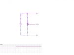
The diagram above is how you should be wiring it to the PICAXE for correct operation, you do-not need any series resistance as it will skew your results. Any non-linearity you are seeing is from the Pot itself, which I presume is a linear type and not a log audio type?
If you want to size the value of a pot, then the general rule of thumb is to make the current through the pot 10x greater than your input current, which in this case is 5uA, so assuming a 5V supply the pot value should be at least 5/50uA = 100K ohms. Anything less than this ensures the pot is not the determinant in the readings, so a 10K pot is very much greater than the PICAXE input effects.
The diagram above is how you should be wiring it to the PICAXE for correct operation, you do-not need any series resistance as it will skew your results. Any non-linearity you are seeing is from the Pot itself, which I presume is a linear type and not a log audio type?
Its a spec that can be difficult to find, but you will see it on the 18M2 (16F1827) datasheet.
The maximum recommended impedance of an analogue voltage source (i.e. the pot) is 10K.
You can go higher if a 10nF capacitor is added to the pin, but no details provided on the data sheet.
Certainly I have noticed that above 10K, the voltage measured on a pot or other potential divider does reduce (from what it should be) if the impedance is above 10K, this may or may not be important to you.
premelec
Senior Member
I think if you actually want the READADC reading to be accurate to 1 LSB AND the current to the pin is actually 5ua a less than 2K source resistance is implied at 255 steps or less than 490 ohms at 1023 steps... Thus the pot would be about 4K or 1K in these two cases. This is derived by looking at the voltage drop at 5ua through the source resistance at 1/2 LSB [lowest Significant Bit] maximum - I hope it's not really that bad but if the current IS 5ua that's what you work with... Please feel free to correct my calculations if I've got it wrong... ")
Calcs 5v / 255 / 2 [1/2 LSB step voltage] = 9.8 mv / 5ua = 1.96K [some rounding...]
Calcs 5v / 255 / 2 [1/2 LSB step voltage] = 9.8 mv / 5ua = 1.96K [some rounding...]
5uA seems very high - that may be the supply current of the A/D converter, not the pin leakage current?After a long search through the Microchip data sheets (it's not obvious) I see the input leakage current is 5uA for the ADC input, so a high input impedance.
Not sure which datasheet you were looking at but the PIC16F1829 (20M2?) datasheet has +/-5 nA, typical +/- 125 nA max as the input leakage spec - pg 362.
The 10K impedance restriction comes about as a result of the need to fully charge the sample and hold cap (Chold, fig 16-4, pg 163) during the sampling period. Adding an external cap to the pin effectively removes this requirement. More details only if you REALLY want them...
I think the ADC issue is not a matter of pure input impedance and ohms law. There are, as I recall, far more ADC inputs than the chip has sample and hold circuits (one in fact). The inputs are multiplexed onto the sample-and-hold. That is one of the reasons that they can't simply be treated as high-Z cmos inputs. The input signals are connected in turn to a capacitor, and it is the charge profile of the capacitor that is measured. The required low impedance is so that the capacitor can be reliably charged in a short time.
(note to self:must type faster in future to avoid repetition!)
(note to self:must type faster in future to avoid repetition!)
There seems to be some confusion between the marked value of a pot, and its source impedance when used as a voltage divider.
Assume a 20K pot with it's end points connected to gnd and +5v.
When the wiper is at one end stop it will see 0v and no impedance, zilch! It is shorted to GND...
Rotated to the other end stop it will see 5v, and again no impedance. This time its shorted to +5.
At the mid point the wiper will have 10K to GND, and 10K to +5. Result is 2.5V, and the impedance is the 2 10K resistors in parallel, or 5K.
So the maximum impedance offered by a pot in this mode is 1/4 of the end-to-end marked value.
BeanieBots
Moderator
I'd like to see that proof as well. Especially as I make it 1/2 end-to-end marked value and not 1/4.
Wow. Thanks, fellas! I kinda get the concept of software manipulation of the data that is generated by the action of the pot, but unfortunately I have a real hard time understanding the math, particularly the algebraic or logarithmic stuff. Whenever I see someone talking about some problem or another being solved by the application of some "simple" equation like w1 = w0 // 6 + 1, I'm lost. I've got to trial-and-error everything and watch carefully for any smoke! It completely gripes my ass that when I was young and had the opportunity to learn math in school, I saw no point to it. Now it fascinates me. Go figure.....
Armp is correct for an AC signal or in electrical terms the impedance seen by the ADC input. But for DC signal paths, the resistance seen is simpler, but only a little bit more!
A 20K port at half-wiper setting will be comprised of two 10K + 10K segments. For a DC signal, the resistance to GND is 10K and to the +5V supply is 10K, the PSU shoudl be considred to have infinite Resistance (you can't (easily) drive a current into the PSU) but it has, or ideally should have a very low impedeance, ideally 0. In electrical terms its impedance is declared as Z = R + jwC and/or JwL where w= 2 Pi F and at DC the Freqeuncy will be 0 so leaving just an R component, that should in-turn be considered to be very high.
So the outcome is the ADC sees 10K for DC currents, but the moment the signal moves around (F is no-longer 0) then the impedance becomes complex and Z = R + JwC or L depending on the characterierstics of the PSU which then become prevalent.
Armp got to 5K because in impedance terms (Not resistive) 10K in parallel with 10K is 5K.
For most practical purpouses you can assume DC conditions. Either way the input impedance of the ADC is much greater than the typical POT in use, so not a problem.
It's all to do with Thevenin's Theorem - a bit heavy for here but if interested take a look at:
http://netlecturer.com/NTOnLine/T08_THEOREMS/p03ThevA.htm
I need coffee before I address some of the issues above - maybe someone else will jump in first...
http://netlecturer.com/NTOnLine/T08_THEOREMS/p03ThevA.htm
I need coffee before I address some of the issues above - maybe someone else will jump in first...
Last edited:
Given 2 resistors R and (20-R) in parallel the resulting resistance isWhat's the proof that it's the MAX?
Rp = R(20-R)/ (R+(20-R))
Rp= ( 20R - R^2) /20
Differentiating wrt R gives
dRp/dR = (20-2R)/20.
This is zero at 20=2R or R=10
Second differential is negative so this is the max
Substituing back gives
Rp = (10*10)/20 = 5
Well - you asked
I used to be a dab hand at Thevenin and his mate, Kirchoff - but the time for that has passed.
"Changing the Law of a Pot" via some parallel fixed resistors at http://sound.westhost.com/pots.htm is quite interesting - but note that the Y-axis of one graph is attenuation, not resistance.
And there's some nice calculators at http://www.sengpielaudio.com/calculator-voltagedivider.htm
Pots - so simple, but so complex at the same time!
For a PICAXE ADC input, you won't go wrong by just using a 10K pot
mrburnette
Senior Member
Which is why we have so many "rules of thumb"...For a PICAXE ADC input, you won't go wrong by just using a 10K pot
There are days that we must design before saturating ourselves with coffee...- Ray
Maybe that's what you call it in Bath, but it Portsmouth we called it differentiating....I'@Armp did you mean 'differentiating' wrt to r, in the UK we'd call that rearranging ?
I think the original core problem evolved to one of understanding how to scale in software without knowing a bunch of maths. Using an 8-bit adc, we note that the input is a value between 0 and 255 inclusive (readadc byte limitation). The output should be between 0 and 65335 (2^16) i.e. a word variable.
The log/exponential function is fairly tricky to compute so I suggest looking at the quadratic function ('squared'). I expect it would be similar in its effect in practice, which is to streeetch the range of numbers preferentially at one end.
If the output = input * input then values at the low end will scale less than high end values, so that 128 * 128 = 16384, but 255 * 255 = 65025. So half the input range covers a quarter of the output range.
So, to scale an input in the range of 1 - 255, square the input. This gives you a number in the full range of a word value, with a quadratic shape. This means that the higher the number the higher the result,with a compression of the scale towards the bottom. I don't know the desired outcome but you can play with this to change the shape, for example, subtracting the input from 255 before the calculation will up-end the scale.
Any linear function is possible provided it scales within the range of a word variable, and you then can use the word variable for whatever is the need, even dividing by 255 and scaling it back to a byte again. If you use a 10-bit adc then you need an additional scale factor to keep the outcome under 65335.
Or you can scale in steps using a select/case statement:
select input
case < 10
output = this
case < 100
output = that
endselect
And you can mix linear and steps if you want.
premelec
Senior Member
Practical Pots
@MartinM57 - I enjoyed looking those references - mechanically pots are made in so many ways and materials - I recall from many years ago in audio work that 'hot molded' carbon pots with a carbon wiper ['AB' type] actually got electrically quieter with mechanical exercise. In my collection I have some 15 T .1% linearity Helipots about 3 inches in diameter - nothing said about the inductance of those thousands of fine wire turns on the fat wire insulated core. Anyhow for those of us around electronic stuff for a long time we know that referring to a component as though it is a simple defined entity doesn't match what actually exists in so many forms all of the same name... I enjoy the diversity! [and sometimes know which item to use...]. One of the least fun rheostats to emulate is the fuel sense wire wound very non-linear type unit... that feeds the thermal bimetal gauge needle indicating [no wonder it's not very accurate] fuel tank levels in autos.
@MartinM57 - I enjoyed looking those references - mechanically pots are made in so many ways and materials - I recall from many years ago in audio work that 'hot molded' carbon pots with a carbon wiper ['AB' type] actually got electrically quieter with mechanical exercise. In my collection I have some 15 T .1% linearity Helipots about 3 inches in diameter - nothing said about the inductance of those thousands of fine wire turns on the fat wire insulated core. Anyhow for those of us around electronic stuff for a long time we know that referring to a component as though it is a simple defined entity doesn't match what actually exists in so many forms all of the same name... I enjoy the diversity! [and sometimes know which item to use...]. One of the least fun rheostats to emulate is the fuel sense wire wound very non-linear type unit... that feeds the thermal bimetal gauge needle indicating [no wonder it's not very accurate] fuel tank levels in autos.
Had my coffee...
The 'typical' number is +/-5nA and you would expect some 90% of all parts to be less than this at room temperature - see discussion on http://www.embeddedrelated.com/groups/piclist/
Basically if the external cap is big IT can supply some of the charge current in parallel with the source impedance.
It is still my opinion that this stuff is not of interest to 99% of the forum members, and should be carried out by PM or on either of the referenced sites above.
And on that bombshell.....
Pull up the appropriate PIC datasheet, and search for "D060". This is the worst case, 85C leakage current, and is +/- 125nA for all M2 parts.After a long search through the Microchip data sheets (it's not obvious) I see the input leakage current is 5uA for the ADC input, so a high input impedance.
The 'typical' number is +/-5nA and you would expect some 90% of all parts to be less than this at room temperature - see discussion on http://www.embeddedrelated.com/groups/piclist/
There are examples on the Microchip site: http://www.microchip.com/forums/tt.aspx?forumid=-2The maximum recommended impedance of an analogue voltage source (i.e. the pot) is 10K.
You can go higher if a 10nF capacitor is added to the pin, but no details provided on the data sheet.
Basically if the external cap is big IT can supply some of the charge current in parallel with the source impedance.
Not sure even now what this is saying.... Power supplies are typically designed to have low impedance from dc to 100s of Khz. They are supplemented with caps at the board and chip level.For a DC signal, the resistance to GND is 10K and to the +5V supply is 10K, the PSU shoudl be considred to have infinite Resistance (you can't (easily) drive a current into the PSU) but it has, or ideally should have a very low impedeance, ideally 0.
It is still my opinion that this stuff is not of interest to 99% of the forum members, and should be carried out by PM or on either of the referenced sites above.
And on that bombshell.....
Last edited:
In analog circuits two general types of pots are used, linear and audio. A linear taper pot has a straight line resistance profile from CW to CCW while a audio taper is designed to match the non-linear response of the human ear to sound pressure levels.Well, I would like to be able to control how much the pot effects the gradient, just like how using a pot in an analog circuit works;
You might want to try a audio taper pot. Or do it in code...
You can do quite a bit in code but you can't change the way a motor works. Due to the way most motors are made they are only effective in a limited RPM range. If this is a small DC motor designed to run at 300 RPM it may not be able to overcome friction to start turning at 30 RPM. For fairly constant torque ove a wide RPM range stepper motors are quite useful.For example, I built a circuit that controls a small fluid pump (DC motor), and using the ADC to control the PWM, I found that there was no way I could get the pump motor to turn very slowly. All I could get it to do was start spinning abruptly and could really only effectively control the speed of it when it was turning way too fast to be of use. In other words I wanted the spread of the pot to control the motor through 0 to about 30 rpm instead of 0 to 300 rpm.
rkjohnsonsr@gmail.com
New Member
There is also the issue of granularity... small changes on a small value pot will be greater than small changes on a large value pot.
Robert K. Johnson Sr.
Robert K. Johnson Sr.
rkjohnsonsr@gmail.com
New Member
An Audio taper pot is a pot that changes in proportion to the human ear dynamic range, logarithmically (Base e)... It would be a very good idea to make sure that the pot is linear taper
rather than log (audio) taper for ratio-metric voltage measurements Set the pot at 25% (about 60 - 70 deg of a 270 deg rotation pot (most common type of pot)) and measure the resistance...
it should be approx 25% of the pot's resistance, if it isn't then you have a log taper pot... In the Olden days there were several different tapers... including reverse taper...
However those are not too common any more. Hope this bit of "Old School" information helps.
Robert K. Johnson Sr.
I understand the low end vs. high end difference (I think), but I'm altogether unsure what you meant by output=input * input. Does it have something to do with converting byte to word so that I can stay within limits?.
If the output = input * input then values at the low end will scale less than high end values, so that 128 * 128 = 16384, but 255 * 255 = 65025. So half the input range covers a quarter of the output range.
And what is a quadratic shape? Is it the same as an exponential curve?
Thanks again!