Driving 4 motors with one L293D with Picaxe 28x1?

MaltiK

Member
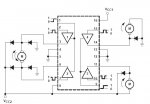
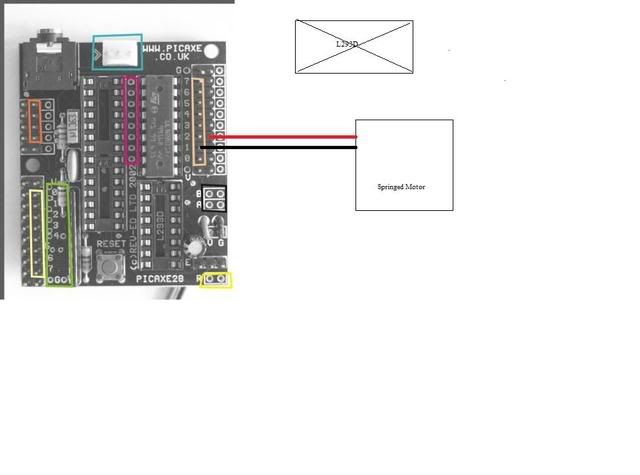
I have two L293Ds and one is in the default DIP socket on the actual board, and the other is external. The external chip, I wish to control four geared motors (they are GM10s if that makes any difference) How do I go about doing this? I already purchased these two radioshack products:

http://www.radioshack.com/product/index.jsp?productId=2062606&cp=&sr=1&kw=dip&origkw=dip&parentPage=search

and

http://www.radioshack.com/product/index.jsp?productId=2103799&cp=2032058.2032230.2032265&parentPage=family

What ports do I use on the chip? Is this even possible, to control 4 motors with one chip? How do I control these if it is? And where do I connect them (outputs, voltages, grounds... etc)
 

Rickharris

Senior Member
It depends what you want to do with them - what sort of motors they are. In general the L293 will control 2 separate motors and provide approx 1.5 Amps of current.

I guess you could set up a separate enable disable line for each motor so they only turned when you wanted them to.
 

westaust55

Moderator
How are you going to use the GM10 motors?

1. Are you going to retain the spring or remove it?
2. Are you using them in single direction or bi-directional?
3. Are you going to use them one at a time, in pairs or possible all four at once?
4. How many PICAXE outputs are available/assigned for the motor control purposes?


as Rick has said, the LD293D is primarily being used for provide bi-directional control for 2 motors each - see current PICAXE manual 3 page 12 - so tentatively possible.

The GM10 motor stall current at 6V is 220mA so the LD293D can handle that as they are rated "600mA OUTPUT CURRENT CAPABILITY
PER CHANNEL" from the ST Electronics data sheet.

The L923D chips have enable pins (pins 1 and 9 on DIP version) so it may be possible to control selection each motor with those signals if not all motors required to run at once.


So really comes down to how you will use them. In other words more information is required to give a clear answer.

EDIT:
If you have the AXE020 board then by default the on-board L923D "enable" pins are permanently connected high.
You may be able to trace the circuit and modify it for control if that is the way you wish/need to go.
 
Last edited:

MaltiK

Member
How are you going to use the GM10 motors?

1. Are you going to retain the spring or remove it?
2. Are you using them in single direction or bi-directional?
3. Are you going to use them one at a time, in pairs or possible all four at once?
4. How many PICAXE outputs are available/assigned for the motor control purposes?


as Rick has said, the LD293D is primarily being used for provide bi-directional control for 2 motors each - see current PICAXE manual 3 page 12 - so tentatively possible.

The GM10 motor stall current at 6V is 220mA so the LD293D can handle that as they are rated "600mA OUTPUT CURRENT CAPABILITY
PER CHANNEL" from the ST Electronics data sheet.

The L923D chips have enable pins (pins 1 and 9 on DIP version) so it may be possible to control selection each motor with those signals if not all motors required to run at once.


So really comes down to how you will use them. In other words more information is required to give a clear answer.

EDIT:
If you have the AXE020 board then by default the on-board L923D "enable" pins are permanently connected high.
You may be able to trace the circuit and modify it for control if that is the way you wish/need to go.
1. I am going to retain the spring
2. Single direction
3. Eventually they will all be used at once
4. Five outputs are available

Ok, so only one of them I believe, according to what you say will be using an external L293D because this one is panning according to the SRF05 I am using, am I wrong?
 

westaust55

Moderator
1. I am going to retain the spring
2. Single direction
3. Eventually they will all be used at once
4. Five outputs are available

Ok, so only one of them I believe, according to what you say will be using an external L293D because this one is panning according to the SRF05 I am using, am I wrong?
When you say panning, and single direction, does this mean you are only going to operate through 60 degrees? Even at around 200 rpm it will be more like a two -position mechanism.

If you used bi-directional then you would have -60 deg, 0 deg and +60 deg settings.

Noting all are to be used with the internal spring so moving from rest to 60 degree rotation when energised and back to 0 deg (rest) position when de-energised, I feel that servos might be a better proposition.


To respond to you last question (previous post), YES you can still use the L923D as the driver for a motor in single direction mode - may not be the most ideal option but will certainly work. See the right side of the attached diagram from the TI datasheet
 

Attachments

Last edited:

MaltiK

Member
Ok then my last question is, for motors that go in a single direction, do I hook the ground to ground on my picaxe, and voltage wire, to an output?
 

westaust55

Moderator
Ok then my last question is, for motors that go in a single direction, do I hook the ground to ground on my picaxe, and voltage wire, to an output?
1. The ground of the motors, the ground of the L923D and the ground of the rest of the PICAXE system should be connected together. This is needed to give a reference level between the PICAXE and the L923D driver chips.

2. Only L923D pins 2, 7, 10 and 15 are connected to the PICAXE. (see manual 3 page 12 however the PICAXE pins need not be the same one's as shown in Manual 3)

3. The L923D pins labelled as Vcc need to be conencted to a voltage level depending upon the motor rating. This may be 4.5V or 5Vdc or may be a different voltage. While you can connect to the same supply voltage as the PICAXE, this may lead to voltage fluctuations when the motors are started causing such things as PICAXE reset. Thus where possible try and use a different power supply for the motors even if they are 5V rated.
 

MaltiK

Member
1. The ground of the motors, the ground of the L923D and the ground of the rest of the PICAXE system should be connected together. This is needed to give a reference level between the PICAXE and the L923D driver chips.

2. Only L923D pins 2, 7, 10 and 15 are connected to the PICAXE. (see manual 3 page 12 however the PICAXE pins need not be the same one's as shown in Manual 3)

3. The L923D pins labelled as Vcc need to be conencted to a voltage level depending upon the motor rating. This may be 4.5V or 5Vdc or may be a different voltage. While you can connect to the same supply voltage as the PICAXE, this may lead to voltage fluctuations when the motors are started causing such things as PICAXE reset. Thus where possible try and use a different power supply for the motors even if they are 5V rated.
Wait, so I get how to connect the bidirectional motor and the spare L293D, but how do I connect the other motors, that only go one direction?
 

westaust55

Moderator
Did you look at the diagram I attached at post 7 ?

For a single direction motor, connect from a L923D output (for example pin 14) to the motor. Then from the motor to ground.

That connection will have the motor operate when the PICAXE output to the L923D input goes high.
 

MaltiK

Member
wait so, even thought they have a spring on it to enable it to go both directions (literally 1 direction), it still needs PWM?
 

BeanieBots

Moderator
You only need PWM if you want to control the motor speed.
For single direction at single speed, a 293D is overkill. A single transistor would do the job just fine.
 

MaltiK

Member
alright, so if i were to describe the wiring would it go:

transistor- output (1) of picaxe and the transistor connected to the motor?
 

westaust55

Moderator
Please clairfy . . . .

Are you:
1. still intending to use the L923D chips as you originally posted
2. decided to go to a FET or other transistor

How about drawing and uploading a schematic diagram showing what you intend to do and we can confirm whether it is right or advise accordingly.
 
Last edited:

MaltiK

Member


Its easy to understand I guess, but it doesnt make sense, if that made sense, the Voltage wire of the SPRINGED motor, connected to the output of the Picaxe, and the ground to ground?

Or if I were to use a transistor (MOSFET /w PWM) would I be hooking the V to output of the transistor and the G to G? and then the motor to the transistor, and I can then control it via high/low
 

westaust55

Moderator
Its easy to understand I guess, but it doesnt make sense, if that made sense, the Voltage wire of the SPRINGED motor, connected to the output of the Picaxe, and the ground to ground?

Or if I were to use a transistor (MOSFET /w PWM) would I be hooking the V to output of the transistor and the G to G? and then the motor to the transistor, and I can then control it via high/low

Okay so it is the AXE020 proto-board ULN2803A darlington transistor pack you are talking about in terms of “transistor”.
You need to learn to give this sort of information up front to make it easy for others to understand what youa re trying to do.
The ULN2803A has a continuous rating of 500mA and a peak rating of 600mA.

The GM10 motor stall current at 6V is 220mA so the ULN2803A can handle the motor starting/stall current.

Therefore it is not essential for further transistors.

Not sure where you have gained the idea that you need PWM to operate this motor. Straight voltage will do the same thing.

So connect the motor +ve terminal to supply voltage and the -ve side of the motor to the desired ULN2803A output.
Have a look at the diagram at the bottom of page 2 of the AXE020 manual/datasheet.
 

MaltiK

Member
Okay so it is the AXE020 proto-board ULN2803A darlington transistor pack you are talking about in terms of “transistor”.
You need to learn to give this sort of information up front to make it easy for others to understand what youa re trying to do.
The ULN2803A has a continuous rating of 500mA and a peak rating of 600mA.

The GM10 motor stall current at 6V is 220mA so the ULN2803A can handle the motor starting/stall current.

Therefore it is not essential for further transistors.

Not sure where you have gained the idea that you need PWM to operate this motor. Straight voltage will do the same thing.

So connect the motor +ve terminal to supply voltage and the -ve side of the motor to the desired ULN2803A output.
Have a look at the diagram at the bottom of page 2 of the AXE020 manual/datasheet.
therrrrr we go... thanks mate well appreciated!!!!
 

BeanieBots

Moderator
Indeed, stating that you had the AXE020, this could have been concluded with a single reply.
We can only help based on the information you give us.
 

MaltiK

Member
Ugh.... its not working, I am connecting one wire on the motor to a G pin on my MCU and the other to a digital output pin, with the transistor in the socket, suggestions? (yes I uploaded the code:)

main:
high 0
wait1
low 0
wait1
goto main
 

eclectic

Moderator
MaltiK

Please look at page 2 of the AXE020 datasheet.

You need one wire to the output, and one wire to V+.

e
 

Mycroft2152

Senior Member
Maltik,

Replace the GM10 with a LED and resistor to make sure the program works.

The output of the PICAXE pin itself is only 25 milliamps. Definitely not enough current to run the GM10 directly. You need some type of transistor to boost the current.

What are you using the GM10's for?

Have you removed the spring for continuous motion? Otherwise you will only get about 60 degrees of rotation. The spring acts as a stop.

Myc
 
Top