Dome Light Dimming with PICAXE

ROGER555

New Member
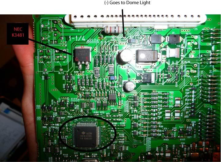
My car has factory theater dimming that fade/on fade/off as you open and close the doors.

The factory system is designed around incandescent bulbs which I have replaced with LEDS and consequently I have lost some of the effect.

The fade/on is gone, the LEDs turn on full bright immediately and the fade/off is rather quick and flicker toward the end (smoothed this out with a cap) I believe the stock system uses PWM but at a frequency not suited for LEDs which causes the flicker toward the end.

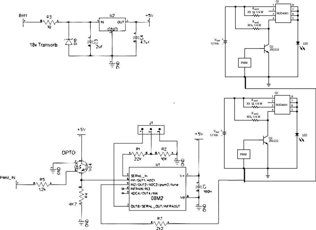
I was thinking about the possibility of using the PICAXE and use the inputs from the OEM system to trigger the PIC and control the fade/on fade/off better.

The LEDs will use a constant current driver with PWM input capabilities. Can I program the PIC to output a 5 seconds fade/up PWM to full brightness and a 5 seconds fade/out triggered by the existing signal from the car?
 

Dippy

Moderator
"I believe the stock system uses PWM ..."
- don't just "believe" , measure it or research it properly.


"Can I program the PIC to output a 5 seconds fade/up PWM to full brightness and a 5 seconds fade/out triggered by the existing signal from the car? "
- probably, almost certainly.


Your next question will , of course, be "how?".

You will need to provide PRECISE specs of the factory signal stream.
Otherwise we'll spend hours guessing.
(well, some of us will ;) )

I won't go on about Automotive elcetronics and safety.
I'll leave Eclectic to search for the answer. :)
 

ROGER555

New Member
"I believe the stock system uses PWM ..."
- don't just "believe" , measure it or research it properly.


"Can I program the PIC to output a 5 seconds fade/up PWM to full brightness and a 5 seconds fade/out triggered by the existing signal from the car? "
- probably, almost certainly.


Your next question will , of course, be "how?".

You will need to provide PRECISE specs of the factory signal stream.
Otherwise we'll spend hours guessing.
(well, some of us will ;) )

I won't go on about Automotive elcetronics and safety.
I'll leave Eclectic to search for the answer. :)

Thank you for the response. Are automotive discussions prohibited here I read the FAQ I didn't see anything and I saw a few post talking about using the PIC for timing on an engine so I figured a question about lights would be acceptable.

As for the outputs of the OEM system I know the dimming is controlled on the low side (-) and almost 100% its a PWM signal due to discussions with others with the same vehicle. I have not attempted to measure the freq/duty cycle of the OEM PWM(or know how to off the top of my head).

Does it really matter though? What if I just had the PIC activated by the (-) PWM trigger once received the PIC would take over and control the LED output fade/up. Once the low signal is lost it could activate the fade/out sequence then loop waiting for the (-) again?

What would the benefit be of knowing the exact freq of PWM (-)?
 

eclectic

Moderator
snipped
As for the outputs of the OEM system I know the dimming is controlled on the low side (-) and almost 100% its a PWM signal due to discussions with others with the same vehicle. I have not attempted to measure the freq/duty cycle of the OEM PWM(or know how to off the top of my head).
Have you got access to a 'scope?

Even a soundcard version on a Laptop may be OK.

e
 

Dippy

Moderator
Well, as you said you "believe" it is PWM then I assumed you didn't know for sure.

If you are sure it is PWM then that's a different matter. I'm sure a triggering-your-own-PWM-duty-fade routine is a good idea ... and easy, just ramp your duty time using a fq that is suitable. Time to have a play.

No, automotive discussions aren't banned. We just have to be careful as we don't know the skill level of the posters. There are aspects of safety, legality and insurance that people often forget about in a moment of passion.
Some of the car-related circuits posted (and in places like Destruc... sorry... Instructables) are , how shall I say it, awful.
And with vehicle electronics becoming more and more complicated then a slight Numpty-Moment could cause all sorts of problems.
So, on this Forum we don't ban per se but we try to discourage especially as there is a huge range of skill level.

And, of course, some engine related questions are about stationary engines or similar where the 3rd party risk is much lower.
In some cases we feel that if you have to ask here then you shouldn't be doing it. I'm not suggesting that applies to you.
Just be careful.
 

ROGER555

New Member
Have you got access to a 'scope?

Even a soundcard version on a Laptop may be OK.

e
No access to a scope or have ever used one for that matter. I do however know what they do! I'm not quite to that level yet just bought my first PICAXE last week. Before that it was just relays, transistors, resistors, diodes and a few 555 timer projects, now I feel the possibilities are endless! Is there some free software and a DIY for a USB interface or inexpensive interface that you would recommend?

Well, as you said you "believe" it is PWM then I assumed you didn't know for sure.

If you are sure it is PWM then that's a different matter. I'm sure a triggering-your-own-PWM-duty-fade routine is a good idea ... and easy, just ramp your duty time using a fq that is suitable. Time to have a play.

No, automotive discussions aren't banned. We just have to be careful as we don't know the skill level of the posters. There are aspects of safety, legality and insurance that people often forget about in a moment of passion.
Some of the car-related circuits posted (and in places like Destruc... sorry... Instructables) are , how shall I say it, awful.
And with vehicle electronics becoming more and more complicated then a slight Numpty-Moment could cause all sorts of problems.
So, on this Forum we don't ban per se but we try to discourage especially as there is a huge range of skill level.

And, of course, some engine related questions are about stationary engines or similar where the 3rd party risk is much lower.
In some cases we feel that if you have to ask here then you shouldn't be doing it. I'm not suggesting that applies to you.
Just be careful.
I understand what your saying and think its good to provide a disclaimer when it comes to automotive projects. I'm just glad discussion is not outright banned like some forums, I think its ridiculous when discussing accessory functions lighting, windows, security which are still easy to interface with safely even with the CANBUS systems.

I might be a noob when it comes to micro controllers so you will find me asking lots and seemingly stupid questions about the interface, but rest assured and I'm very capable when it comes to vehicle wiring & safety in general especially my car.

So back to me being a noob, I am using logicator now for programming. I know there is a PWM out option but do you know if I will be able to achieve what I want to do in logicator or will I need some basic code? I know I'll just have to mess around with it probably.

I just found this too I might find some answers here
http://www.picaxeforum.co.uk/archive/index.php/t-12541.html
 

Dippy

Moderator
Sorry, I know nothing about Logicator. Others here use it, but I'd recommend using normal code but that's just me.
.... then you can read up about PWM and Duty in Manual 2 (BASIC). :)

I'd practice ramping the PWM duty before doing the sense bit.
Start simple and build the programme.

Yes, we're an open minded lot here, but we would never encourage people to stray into potentially risky projects especially when it's well beyond the competence level.
We all think we are cleverer than we really are , but we learn our limits. We've all been there, rush in, have a bash, but some mistakes can have horrible consequences and we don't want that.
On the other hand, if no-one discusses the principles then how do you learn?
It's a balance but we err on the side of caution.

Similar applies to electric Mains projects. Some people haven't a clue and are a danger to themselves and others. (I was like that once and learnt the hard way. I don't want others to copy that.)


I work in electronic power systems for electric vehicles and the precautions we take are enormous. Loads of volts and amps and big semiconductors with water cooling. Oh, and it's really easy to screw CAN if you aren't careful by the way :rolleyes:

Anyway, start simple and get the first bit going.

PS. No need to quote huge chunks of my drivel...
 

eclectic

Moderator
@ROGER555

Please tell us what Picaxe chips
and other equipment you own.
Then, you're likely to receive suggestions
for circuits and programs.

There is a mass of information regarding
Pwmout and dimming here on the Forum.

Once you have built a couple of real (breadboarded) circuits,
it will become much easier.

e
 

ROGER555

New Member
I have several 08M2 & 18M2 chips and i'm currently using Logicator. I also bought the AXE021 & CHI030A project boards anda relatively large collection of additional electronics supply. I know a relative statement but I have digital/adjustable power supply lots of resistors,caps, 555 timers, transistors, MOSFETS, LEDs, drivers, relays.

I know what you mean about getting on the boards but without doing some reading I'm still not sure quite where to start with the duty & cycles setting.
 
Last edited:

John West

Senior Member
You might start with about a 10 kHz PWM frequency and a 90% duty cycle. That will likely be a fast enough pulse rate that you won't see it, (especially if you parallel a capacitor across the LED module.)

The 90% duty cycle will mean the light will be nearly full brightness, assuming your LED module runs on the full battery voltage. Then experiment with lower duty cycle percentages until the light just goes out at perhaps 20 or 30%. Then use those values to establish a range of dimming control that suits you.

A note of warning about motor vehicle PICAXE projects. Even if the circuit is only applied to non-safety or non-vehicle control applications, the PICAXE is still running off of what is often very "dirty" power from the vehicle electrical system. With concerns such as major voltage drops during vehicle start-up to electrical noise from spark plugs and alternators, good filtration of the incoming voltage is an absolute must for reliable automotive electronics. Also, a PICAXE system reset circuit should be considered in the event that the filtration installed is not enough to provide entirely reliable power.
 

eclectic

Moderator
Good background reading:
Latest Manuals which are included with PE 5.40

M1 p.10

M2 p. 164- 167

M3 p. 7 - 9

The Pwm Wizard.

This works with an 08M2
Code:
#picaxe 08M2
setfreq M4
#terminal 4800

pwmout 2, 99, 0  ; Switch on Pwmout to 0% duty
; 10kHz from Wizard
;Duty varies between 0 - 396
;LED and 300Ohm resistor on Pin2 (leg 5)

Symbol bright = W0

main:

For Bright = 0 to 396 step 10 ;increase brightness

Pwmduty C.2, bright
Sertxd (#bright, " ") ; just for testing

pause 100

next

Pause 1000; 1 second at full

For Bright = 396 to 0 step -10 ; decrease

Pwmduty C.2, bright
Sertxd (#bright, " ") ; just for testing

pause 100

next

Pause 1000 ; 1 second at zero

Goto Main
I'll leave the Automotive aspects to the experts.

e
 

techElder

Well-known member
Wouldn't it be better to use the dimming system that the car already has? Perhaps make the LED dome light look more like an incandescent lamp to the in-car dimming system?

If the current dimming system is "low side" based, where will you position your alternative dimming system in the circuit?

You really need to post a schematic of what you have now, before you can start designing a program for a PICAXE.

PS. Sounds like an analog problem to me.
 

morrismarine

New Member
I have several 08M2 & 18M2 chips and i'm currently using Logicator.
As a point i found Logicator rather useful but at the same time a bit limited, for example with PWM there didnt seem to be an abiltiy to modify the variables, what it was useful for was creating a basic sketch of the program (and in my case its a basic sketch of a basic program) tehn convert it to basic to see how the code is complied, this then let me develop my understanding of programming using basic in the PICAXE PE much better.
 

Goeytex

Senior Member
It seems to me that you need to know what the signal is that drives the original incandescent lamp before you can proceed with developing your picaxe project and code.

If it is a PWM that's one thing. If it is an analog signal thats anothe'r. With an
incandescent my GUESS is that it is analog. But I suppose it could be a PWM. The best way to tell is to borrow a scope from someone and look at it.

An analog meter "might" be able to show if it is analog. Many digital multimeters have a frequency counter function. This could tell if it is a PWM if you read a frequency of greater than about 200 Hz as the lamp is fading up or down. If it does not show a frequency reading then it is probably an analog signal.

As far as the clamoring that always comes up when anything Automotive is mentioned .... It can be annoying but it is necessary.

Protection circuitry is needed to protect the Picaxe and any other sensitive devices on your circuit since it is in an automotive environment where voltage transients can be as high as 60v. There is lots of stuff on the Internet on how to approach this. Look for Application Notes at National Semiconductor, Fairchild, Maxim and other IC manufacturers.

ST Micro makes "Transil" diodes. Some call these "transorbs". These work in conjunction with a series current limit resistor to quickly "absorb" transients.
ST has some good App Notes. Your voltage regulator should be an Automotive Grade LDO.

You can over do it here. My guess is all that you will need in your application
is something like an LM9076 or LM 9071 Regulator that has built in transient suppression. Read the datasheet and follow the MFG recommendations.

Goey
 

ROGER555

New Member
Good background reading:
Latest Manuals which are included with PE 5.40

M1 p.10

M2 p. 164- 167

M3 p. 7 - 9

The Pwm Wizard.

This works with an 08M2
Code:
#picaxe 08M2
setfreq M4
#terminal 4800

pwmout 2, 99, 0  ; Switch on Pwmout to 0% duty
; 10kHz from Wizard
;Duty varies between 0 - 396
;LED and 300Ohm resistor on Pin2 (leg 5)

Symbol bright = W0

main:

For Bright = 0 to 396 step 10 ;increase brightness

Pwmduty C.2, bright
Sertxd (#bright, " ") ; just for testing

pause 100

next

Pause 1000; 1 second at full

For Bright = 396 to 0 step -10 ; decrease

Pwmduty C.2, bright
Sertxd (#bright, " ") ; just for testing

pause 100

next

Pause 1000 ; 1 second at zero

Goto Main
I'll leave the Automotive aspects to the experts.

e
Thank you sir! gives me a place to start!

Wouldn't it be better to use the dimming system that the car already has? Perhaps make the LED dome light look more like an incandescent lamp to the in-car dimming system?

If the current dimming system is "low side" based, where will you position your alternative dimming system in the circuit?

You really need to post a schematic of what you have now, before you can start designing a program for a PICAXE.

PS. Sounds like an analog problem to me.
I was just going to power the PICAXE using a 5v regulator and the fixed 12v source at the dome light & chassis ground.

Then use the PICAXE as a bypass between the switched ground and the LEDs. Once input low is received from the switched ground the PICAXE program takes over (fade/on). Once input Low is lost PICAXE activates Fade/off. Cant the PICAXE be set to activate from this low input regardless of whether its a PWM or analog low?


It seems to me that you need to know what the signal is that drives the original incandescent lamp before you can proceed with developing your picaxe project and code.

If it is a PWM that's one thing. If it is an analog signal thats anothe'r. With an
incandescent my GUESS is that it is analog. But I suppose it could be a PWM. The best way to tell is to borrow a scope from someone and look at it.

An analog meter "might" be able to show if it is analog. Many digital multimeters have a frequency counter function. This could tell if it is a PWM if you read a frequency of greater than about 200 Hz as the lamp is fading up or down. If it does not show a frequency reading then it is probably an analog signal.

As far as the clamoring that always comes up when anything Automotive is mentioned .... It can be annoying but it is necessary.

Protection circuitry is needed to protect the Picaxe and any other sensitive devices on your circuit since it is in an automotive environment where voltage transients can be as high as 60v. There is lots of stuff on the Internet on how to approach this. Look for Application Notes at National Semiconductor, Fairchild, Maxim and other IC manufacturers.

ST Micro makes "Transil" diodes. Some call these "transorbs". These work in conjunction with a series current limit resistor to quickly "absorb" transients.
ST has some good App Notes. Your voltage regulator should be an Automotive Grade LDO.

You can over do it here. My guess is all that you will need in your application
is something like an LM9076 or LM 9071 Regulator that has built in transient suppression. Read the datasheet and follow the MFG recommendations.

Goey

I'll try and find out if its a PWM for sure, I heard if I connect a led with a long wire and swing it in the air you will actually see the LED pulsing in the air. Also it looks like my voltage meter has a freq settting.

As for the noisy automotive input voltages I know this is true to a certain level but but generally I think it is better with some of the newer vehicles that use a lot of micro controllers themselves in the CANBUS system. The dome lights are already controlled through the MICU (multiplex integrated control unit) (FYI I have a 2006 Acura TL).

I was searching around for the LM9076 and found its quite expensive at $2+/ea and surface mount only. The LM9071T I couldn't find for sale but there is a hole through version I would prefer. I was planning on trying some of these I had laying around (link below) but I don't think its technically automotive grade.
http://www.fairchildsemi.com/ds/LM/LM7805.pdf
 

ROGER555

New Member
Well I have doubts about my multimeter it does to weird stuff sometimes but i'm not getting a freq reading at all from the dome light. It does give me 60hz when I stick it in the AC socket though its working I guess. Does this mean analog signal or inconclusive?
 

eclectic

Moderator
Well I have doubts about my multimeter it does to weird stuff sometimes but i'm not getting a freq reading at all from the dome light. It does give me 60hz when I stick it in the AC socket though its working I guess. Does this mean analog signal or inconclusive?
It might mean

Oscilloscope. :)

Borrow or download. :)
 

Dippy

Moderator
Is the 'controller' switching the dome lights to ground or are they sourcing the power. i.e. are they high-side or low-side switching.
This is why I posted my qus in post#2.
You have to be SURE of your signals etc. before you can produce a reliable (and electrically safe) device. You may get lucky with a guess ;)
DMM - almost certainly wasting your time, sorry. Time for a 'scope.
 

westaust55

Moderator
@roger555,
If I may make a suggestion, please don't copy the entire post from others with your reply below.
Try to extract and quote just the relevant portion, or alternatively just address the other member with by forum name with a prefixed "@" symbol.
It can become tedious scrolling down through paragraphs one has just read in the prior post just to get to a one-line response (particularly on a small screen when mobile).
 

ROGER555

New Member
Ok maybe this will mean something to someone a bit more knowledgeable. I have a spare MICU and I was able to track down where the (-) output for the dome light comes in the MICU passes through a resistor and into the drain of the P-Channel MOSFET (Datasheet below). I can sort of trace the Gate down to the unidentified IC circled at the bottom. The source look like it goes there too but also have another input from an unidentified source up toward the terminal blocks.


Datasheet for P channel MOSFET 2SK3481 in picture
http://www.datasheetcatalog.org/datasheets2/78/78418_1.pdf
 

ROGER555

New Member
I think my heads going to explode! Just spend the last two nights after work reading about interfacing the PICAXE with automotive power supplies etc. I have like 10 diagrams printed from various threads and still no closer to deciding on which one to use.

Lets say for the main power supply I want to use the LM2940 wiring per the datasheet "typical application" plus add a Transil diode like mentioned above. Where does the diode go? On the 12v side before the relay with a 12v clamp or after the relay with a 5v clamp? I really don't want to stir up another suggestion debate I just want something simple and reliable but not necessary BULLETPROOF considering my vehicle is new, has lots of tech & most likely "relatively" clean voltage and my project does not perform critical safety functions.

Next for the IN/OUTS I think i'm leaning toward a opti isolator for this project & another automotive project (I wont get into right now). I couldn't find many diagrams using the Optio isolators though can someone elaborate on what components I will need in front and around the optio for a PIC input? I did find these that someone suggested on another forum, do they look like they might do the job?

http://www.cel.com/pdf/datasheets/ps2505.pdf
 

Dippy

Moderator
Transils come in 2 basic types; unidirectional (sort of zener diode) and bi-directional.
They come in many values and you'd study the Data Sheet to see their values for the various voltage parameters (clamping, breakdown, standoff).

If you use the unidirectional type it acts like a zener and you place it between the +12V(nom) and Ground. You have it pointing towards the positive. So, at normal voltages it's like having a normal diode and bugger-all current passes.
When a spike comes along it briefly 'passes' that spike through to ground.

Whether or not you use optos depends on the application.
For a digital input it's very useful as long as the input has enough ooomph to make an LED (inside the opto) to switch on.
The output (assuming a transistor type) is as it says on the tin; a transistor.
Thus you design your circuit just like a transistor.

Normally you's just need a limiting resistor on the input (LED side) for 12V a 2K2 would be OK depending on the Opto Data Sheet.
On the output you'd have a pullup or pulldown; 10K would be fine.
Therefore, unless there are other unmentioned issues; opto + 2 resistors.

What is your electronics skill level? I take it all this is new to you?
 

Goeytex

Senior Member
I think my heads going to explode! Just spend the last two nights after work reading about interfacing the PICAXE with automotive power supplies etc. I have like 10 diagrams printed from various threads and still no closer to deciding on which one to use.

Lets say for the main power supply I want to use the LM2940 wiring per the datasheet "typical application" plus add a Transil diode like mentioned above. Where does the diode go? On the 12v side before the relay with a 12v clamp or after the relay with a 5v clamp? I really don't want to stir up another suggestion debate I just want something simple and reliable but not necessary BULLETPROOF considering my vehicle is new, has lots of tech & most likely "relatively" clean voltage and my project does not perform critical safety functions.

Next for the IN/OUTS I think i'm leaning toward a opti isolator for this project & another automotive project (I wont get into right now). I couldn't find many diagrams using the Optio isolators though can someone elaborate on what components I will need in front and around the optio for a PIC input? I did find these that someone suggested on another forum, do they look like they might do the job?

http://www.cel.com/pdf/datasheets/ps2505.pdf
This is what I use to power a Picaxe Circuit on an ATV with a rather noisy alternator. Have never blown a board in over 50 races. This should be more than adequate for your application.
 

Attachments

Last edited:

ROGER555

New Member
Transils come in 2 basic types; unidirectional (sort of zener diode) and bi-directional.
They come in many values and you'd study the Data Sheet to see their values for the various voltage parameters (clamping, breakdown, standoff).

If you use the unidirectional type it acts like a zener and you place it between the +12V(nom) and Ground. You have it pointing towards the positive. So, at normal voltages it's like having a normal diode and bugger-all current passes.
When a spike comes along it briefly 'passes' that spike through to ground.

Whether or not you use optos depends on the application.
For a digital input it's very useful as long as the input has enough ooomph to make an LED (inside the opto) to switch on.
The output (assuming a transistor type) is as it says on the tin; a transistor.
Thus you design your circuit just like a transistor.

Normally you's just need a limiting resistor on the input (LED side) for 12V a 2K2 would be OK depending on the Opto Data Sheet.
On the output you'd have a pullup or pulldown; 10K would be fine.
Therefore, unless there are other unmentioned issues; opto + 2 resistors.

What is your electronics skill level? I take it all this is new to you?
Thanks Dippy! Yes this is all new to me first PIC project so lots to learn. Do you think the datasheet I posted for the Optio would work assuming my inputs/output can easily light the LEDs?

This is what I use to power a Picaxe Circuit on an ATV with a rather noisy alternator. Have never blown a board in over 50 races. This should be more than adequate for your application.
Thanks! Looks good! Is that just a resistor in front 10ohm 1W? Also tantalum caps for the 22uf?
 

Goeytex

Senior Member
Thanks! Looks good! Is that just a resistor in front 10ohm 1W? Also tantalum caps for the 22uf?
Yes, just a resistor. Tantalum cap is unnecessary. A medium to low ESR Electrolytic should suffice. Use whatever the datasheet for the regulator you have chosen recommends.

As far as the opto goes ( I speak only for myself) the one you posted should do ok. But I question the need for optos in the first place in your application. Why do you believe you need optos ?

One of my areas of expertise happens to be in LED lighting. I have designed and prototyped LED lighting systems ranging from simple LED under counter track lighting, to military systems used by the USAF and National Guard for use in Iraq & Afghanistan. In every case I used a Picaxe for initial design. proof of concept and and prototyping.

May I suggest that you:

1. Provide the part numbers and/or or specs of the LEDs that you intend to use. A Datasheet would be most helpful.

  • What is the forward voltage of your LEDs?
  • How much current does each LED draw at max forward voltage? At nominal forward voltage ?
  • How many LEDs do you plan to use ? Lots of cheap small ones or one or 2 Bigger ones ( Cree, Luxeon ,etc)
  • Will the LED's be wired in series, parallel or a combination matrix?
  • Do you plan to use the same regulated supply for the LED's as for the Microprocessor or to drive the LED
    with regulated 12v tapped from the Auto Fuse / accessory Panel ?
  • Have you considered that High Power LEDS many times need to be heat sinked, either through their leads to a
    copper area on the PCB ... directly to a star type PCB and then to an aluminum or copper heat sink ?
  • What was the wattage of the original incandescent Lamp ?
    (A single 3 Watt LED can provide almost as much as much light a 30 watt incandescent)

2. Draw up and post a complete schematic of your project. This can be conceptual , but detailed is much better. Include every component with values if possible. If you cannot for some reason do a schematic, then at least provide a nice block diagram showing Inputs, Outputs/ PWM's, Power sources and LEDs.

If you will do these things, then I and others here with similar expertise & experience will be able to help you along much better and possibly save you a lot of unnecessary grief and frustration.

Goey
 
Last edited:

ROGER555

New Member
Well from the factory I had (4) Dome lights in the vehicle 2 front/ 2 rear

-Front #904 MINIATURE BULB GLASS WEDGE BASE - 13.5 Volt 0.69 Amp
-Rear #2825 MINIATURE BULB MINIATURE WEDGE BASE - 12 Volt 0.4 Amp

Right now I have 4 LEDs in place of each incandescent. I have them wired currently with resistors only no Vreg (I know for shame) for many months now. They are connected series of 3 then the 4th LED has a separate separate resistor. Off the top of my head I don’t remember the resistor values but I had calculated them to run at 50ma @ 14volts. (These are my favorite white LEDs wonderful color & extremely bright for there size, and the fact that it does not need extra heat sinking makes them my go to for many projects)

Nichia Superflux style LEDs
http://www.nichia.co.jp/specification/en/product/led/NSPWR70CS-K1-E.pdf

Forward Current: 60ma
Forward V: 3.1 typical
Luminous Flux: 20lm

I do plan to add a regulator to the actual LEDs when I incorporate the PICAXE so I am open to suggestions on that but typically I would use a 9V Sharp relay (PQ05RD21) and the appropriate resistors. I know they are not automotive grade but I use them all the time and so do the guys on the HidPlanet forum and I have yet to hear of a failure.

Also I have not been able to confirm the signals from the stock lights are PWM and I don’t have a scope so I don’t know how I would figure this out yet. Also yes I would power the PICAXE off the same 12V source.

What are you thinking besides Optos? These are really for my other main project but they seem like a cheap easy way to isolate the PIC regardless of the application.

Thanks for the input thought! I’ll work on a diagram for everything like you requested!
 

MikeM100

Member
Gamma Correction

The problem with dimming LEDS is the non linearity (Gamma) of light output ! I resorted to a 'look up' table to correct for this as a linear ramp is not visually pleasing.

Code:
'LED Dimmer Controller
'Filename: Dimmer.bas
'Using PICAxe-18X (later -08M) with MOSFET LED driver
'Mike Meakin - November 2009
'Last Modified: 20/11/09

'Inputs
symbol updown = pin1 'Up/down Control Input
'Outputs 
 
'Constants
 
'Registers  
symbol  duty  = w0  'Word variable for 10 bit PWM duty Cycle
symbol timer1 = w1  'Word variable for Auto Off Timer 
symbol point = b6  'Table Pointer - Byte

' ***** Initialise PicAxe on Power Up *****
init:
 point = 0   'Clear Table Pointer
 duty = 0   'Set Initial PWM Value to Zero
 pwmout 3, 250, duty 'Duty - 10 Bits - 0 to 1000 max
    'Duty cycle should not exceed 4 x the period

' ***** Programme Starts Here *****
main:      'Main Programme loop
 gosub gamma    'Set LED Brightness every loop
 
 pause 10    '10ms per loop
 if updown = 0 then dimdn  'Test Up/Down Input every 10mS
 
 point = point + 1 max 128 'Brighten Up until maximum value
 goto main
dimdn:  
 point = point - 1 min 1  'Dim Down until minimum value
 goto main
 
' ***** LED Gamma Look Up Table for LED Brightness Linearisation *****
gamma:
 lookup point, 
(0,0,1,1,1,1,1,1,1,1,1,1,2,2,2,2,2,2,2,2,2,2,2,2,2,2,3,3,3,4,4,5,6,6,6,7,8,9,9,10,11,12,13,14,16,17,1
8,20,21,24,25,27,29,31,34,36,39,42,45,48,51,54,58,61,65,70,74,79,83,88,94,98,102,110,110,118,126,134,
142,150,157,165,173,181,189,197,205,220,228,236,252,260,276,283,299,307,323,339,354,370,386,394,417,4
33,449,465,480,504,520,543,559,583,606,622,646,669,693,717,740,772,795,819,850,874,906,937,969,1000),
duty
 pwmout 3, 250, duty  'Set PWM Duty Cycle with value from table

 return    'End of Subroutine
 

eclectic

Moderator
Also I have not been able to confirm the signals from the stock lights are PWM
and I don’t have a scope so I don’t know how I would figure this out yet.
Three possibilities, two free; one not.

1. A soundcard software 'scope.
2. Ask your contacts on the HidPlanet forum if anyone has 'scoped the supply.

2. Buy a 'scope? They really are useful tools.

e
 

Dippy

Moderator
In your setup (and I have no idea what a dome light is) I assume you have simply removed a bulb and replaced it with LEDs+resistors. And this was unsatisfactory visually?

Do these dome lights illuminate when opening the door or switch off the ignition or something like that?

With a 'normal' lightbulb PWM/duty can be relatively slow as there is a certain amount of 'inertia' (heat capacity) in a filament which smooths out flicker. LEDs are quick and will show flicker.

So, why not put the res+optocoupler where the bulb was and use EDGE triggering to initiate your PICAXE fade routine?
Once you have triggered your code you then ignore the input until your fade routine has completed.
It's a simple matter of choosing a fairly fast PWM frequency and gradually reducing duty from nominally 100% down to 0% in an acceptable time.

Using that method it doesn't matter about the Fq/Duty of the original source.
With a small logic FET as the 'switch' you won't need a driver.
 

ROGER555

New Member
In your setup (and I have no idea what a dome light is) I assume you have simply removed a bulb and replaced it with LEDs+resistors. And this was unsatisfactory visually?
Dome/map light what do you call it? But yes essentially the LEDs function fine but I lost most of the slow start and slow fade effects.


Do these dome lights illuminate when opening the door or switch off the ignition or something like that?
Yes they activate when you open the door or unlock the car with the keyless remote.

With a 'normal' lightbulb PWM/duty can be relatively slow as there is a certain amount of 'inertia' (heat capacity) in a filament which smooths out flicker. LEDs are quick and will show flicker.

Exactly!

So, why not put the res+optocoupler where the bulb was and use EDGE triggering to initiate your PICAXE fade routine?
Once you have triggered your code you then ignore the input until your fade routine has completed.
It's a simple matter of choosing a fairly fast PWM frequency and gradually reducing duty from nominally 100% down to 0% in an acceptable time.

Using that method it doesn't matter about the Fq/Duty of the original source.
With a small logic FET as the 'switch' you won't need a driver.
This is exactly what I wanted to do!! Thats why I keep asking why the signal type of the OEM systems matters if I just want to use it as a trigger for the PIC nothing more.

What exactly is EDGE triggering?
 

Dippy

Moderator
Edge triggering is where you )your code or your PICAXE) keeps an eye out for a change in pin status - was it low and it has now gone high? or vice versa..
Most PICs and X2 PICAXEs can do it in an interrupt - you specify rising or falling edge and it does the businees ... obviously this relies on your code. (HINTSETUP in the BASIC Manual 2 - look it up).

Therefore, you can have your optoiso connected to a suitable PICAXE input oin an X2 and when the main car electrical does it's first blink this can trigger your fade routine. And you can arrange it to ignore any further triggers until your routine has finished.
It should be pretty simple but I'm afraid I haven't got the time to write the code or do a schematic.

When choosing transient suppressors make sure you choose a value that does bugger all at 14 to 15V and starts passing lumps (ooer) at 20V or more . Parallel it with a ceramic cap. Have a fuse in series with whole thing and a suitable choke wouldnæt go amiss either.

There, that's youre shopping list done.
Get drawing a schematic and post it here.:)
 
Last edited:

Goeytex

Senior Member
Ok, so you have identified the FET that drives the dome lamps. You wrote that it is a "P channel MOSFET" and then provided the Datasheet for a 2SK3481 N Channel MOSFET. I'm betting is is an N Channel and not a P channel.

If we assume that it is an N Channel and that the signal is a PWM then all you really need to do is what Dippy suggested. Use the original PWM signal to initiate the fade routine in the Picaxe Program. This can be done by programing the Picaxe to detect the leading edge of the first PWM pulse. It can be interrupt driven or done with a loop that includes an "if pinx = 1 then goto fade".

We can take the signal directly from the gate of the Mosfet to trigger the fade routine. That is assuming that it is a 5 volt logic level signal. However we cannot make that assumption as the MOSFET datasheet is unclear as to the gate threshold voltage level. It may or may not be a logic level FET. And since you have no scope we are clueless as to the voltage level of the PWM at the gate of the MOSFET. This is where an opto can come in handy ... When you are scopeless and clueless and don't want to blow your micro. Not necessarily for isolation, since it is highly unlikely that any signals coming off that control board are anything but clean.

Let's assume that the PWM signal is 12 volts at the gate of the Mosfet. ( It could be 5v but we don't know). Arghhh .. NO SCOPE! . The Opto needs about 10 ma to assure full turn on (saturation). So 12 v / 10 ma = 1200 ohms. So we put a 1200 ohm resistor in series with the Opto Diode. If the opto fails to turn on, then it is likely that the PWM at the MOSFET gate is 5v instead of 12. In that case the resistor value needs to be reduced to 470 ohms.

We put a 4.7k Pulldown on the emitter of the OPTO. This gives about 1 ma of current through the opto transistor when it turns on. We take the voltage signal across the resistor and send it to an input pin on the Picaxe. The Picaxe then detects the leading edge of the first PWM pulse and jumps to the fade routine.

The simplified code looks something like this for a "fade in". This is just to give you an idea of how it can work, You could use an interrupt instead. You will also have to figure out how to detect a "fade out" (assuming the dome light fades both in and out). You really really need a scope to do stuff like this. Without one you are pretty lost and in guess mode way too much.

Code:
#picaxe 08M2
setfreq M8
symbol duty = w2
let duty = 0

Main:
do
if pin1 = 1 then goto fade   [COLOR="#008000"] ' waiting for signal [/COLOR]
loop

fade:   [COLOR="#008000"]  'signal detected[/COLOR]
pwmout pwmdiv16, 2, 124, Duty

 for duty = 1 to 500
   pwmduty 2, duty
   pause 20
next duty
pause 1000
goto main
The attached schematic should give you a general idea of how to use the OPTO with a Picaxe.

If it were me, I would get my meter out and find a good source of 5v right off of that control board vs adding a regulator/transorb. The 5v would only
supply the Picaxe & Opto and only draw a few milliamps. I would drive the LED's with regulated 12v from the power bus and not worry about having to
add a 12v regulator. I show using a power mosfet driver and a non logic level power mosfet to drive the LED's. This gives a bit of extra protection
to the Picaxe. However , the MOSFET driver could be eliminated an a logic level FET used at the expense of efficiency and protection. If you
choose to eliminate the FET driver and use a logic level FET, be sure to put a resistor in series from the Picaxe output to the gate of the MOSFET.
 

Attachments

Last edited:

Dippy

Moderator
Nice one Goey, though I wouldn't recommend tapping into the circuit to anyone who is new.

If you have identified the MOSFET correctly it is an N channel.
However, without a 'scope you don't know if it is acting as a low side switch or a high side.
I would therefore recommend either a series diode with your opto (many LEDs wouldn't like a Vr of 12V or more) or , easier, an AC input opto which is simply back to back LEDs. Thus with the series R you can shove it in any way round.


I'm more of a switch low-side for optos but that's just my preference. I'm sure Goeys opto section would be fine for quite a wide range of 'input' ressistor.
It depends on CTR and Goey's R4 as to how it behaves wrt PICAXE DIO. Again, I'm sure that value is not crucial within a range.
If I were you ,Roger, I would breadboard the opto stage on it's own. Bit of breadboard. A crude test would be to put a high-brightness LED in series with R4. It should follow the input.
I would suggest putting a resistor between opto and PICAXE, this could save an accident if you muddle your supplies.
Otherwise it looks good and I would suggest asking for a 'scope for your birthday.
With a 'scope to get precise results and proper data you could do the whole design and breadboard proto in a morning.... ish.
 

ROGER555

New Member
Awesome Goey! I really appreciate you and everyone for that matter helping me out. I've been pretty busy myself so thats why I haven't been posting diagrams or testing yet.

Now to answer some of your questions. Now I know I posted the picture of the MICU unit/fusebox but that is on my spare unit. I wouldn't be able to get to the gate of the MOSFET on the MICU on my car without removing about 50 harnesses and prying the unit open (plastic welded). I need to use the signals i'm getting at the dome light to activate the Optios.

Now to complicate this even further I should let you know that each map light (4) front (2) can each be activated individually by pushing them in also you can control them by flipping a 3 way switch (on/auto/off). The way it works is there is constant 12V (+) supply and they are activated on the low side through the MICU in "AUTO" mode (I know already established this). Switching the master switch "ON" switches all 4 lights from the (MICU "PWM") to fixed ground. Back in "AUTO" mode you can push in on any of the 4 lights which will provide a ground to only that light.

P.S. I know its not conclusive to say it is in fact a PWM signal, but with the stock bulbs you could definitely tell that when they were switched "ON" and running on fixed ground they were brighter then fully light up on the MICU "PWM" low signal.

This should be helpful I took 2 pages from the HELM and photoshopped them together
http://i6.photobucket.com/albums/y225/LegendGS/InteriorLightsDIAGRAM.png

A few comments about the PIC program code. This is what I was thinking. Once pin 1 goes low when I open my door I want a gradual fade to full brightness (3-5 seconds). The lights should stay on until the low signal is lost which is 5 seconds (In the car HUD display I can select between a 5/15/30 second light operation before dimming takes place from OEM). So the PICAXE should keep the LEDs on and continue to check for 1 being low. Once the low is lost the PICAXE should activate a slow ~5 seconds fade routine off then loop and wait. HOWEVER if at some point during the fade/off routine I open my door again I need the routine to either active full bright immediately, jump to the slow rise routine from the beginning or even better yet (probably not possible) Pick up where the fade/out routine stopped and reverse and fade up to full brightness.

Also I dont really want to focus on the LEDs but in your diagram you put 4 LEDs in series and the Vf would exceed 12V. 3 per location might not be enough so I'm thinking about using some 350-700mah Rebels (1) per location with this driver NUD4001 (data sheet below). It will accept a PWM input and looks prefect for my application.

It talks a lot about the PWM frequency and duty cycle in the application notes.
NUD4001 Datasheet
http://www.onsemi.com/pub/Collateral/NUD4001-D.PDF
NUD4001 Application Notes (PWM specific)
http://www.onsemi.com/pub_link/Collateral/AND8234-D.PDF

Maybe something like this for the fronts?


Thoughts/comments/suggestions from everyone greatly appreciated!!!
 
Last edited:

Dippy

Moderator
I've no experience of NUD4001 but I see you've cut'n'paste from data sheet so that's fine hopefully.
However, your cut'n'paste does go a little astray as it looks like you are sending your PICAXE PWM to ground. I'm sure thats just a sketcho.;)

Should you add a transorb and/or diode to the NUD4001 supply? I see nothing in data sheet about reverse polarity or large transient/HF protection/suppression.
As I work in automotive power design we tend to take a belt and braces (what if?) approach.

Personally, I'd add a choke and ceramic cap on input for more effective transient/rf suppression.

Also as I said in my previous post; are you sure about PWM polarity? If you connect that opto to your car incorrectly you could have excessive Vr for the LED. A diode or AC opto would cure that flaw instantly.

No fuse? Tsk tsk , but good luck with project.
 

ROGER555

New Member
Well I should have all the parts here by the weekend to start prototyping.

Dippy- Your saying add a fuse to protect the whole circuit? The OEM circuit is fused at 5a is that ok or did you have something else in mind? As for the choke/cap are you talking about adding this before the 5V regulator? Any chance for some specs on the choke/cap and where exactly you would put it? I'm not familiar with chokes.

Geoytex- Any addition input on the function of the PWM circuit? Also I think I'll be using the CAT4101 LED Driver instead of the one I posted above, but no reason to discuss this part really. Getting the PWM program to function like I want will be the hardest part for me.
 

ROGER555

New Member
Well good news I have it all wired up on a breadboard with the optos and everything. Now I just need to figure out the PWM freq/cycle. Also my results below might vary with my actual LED, this test was done with just a single 3mm 330ohm resistor just for a quick test.

The first cycle posted by Eclectic is very choppy a flickers as it dims.

Code:
#picaxe 08M2
setfreq M4
#terminal 4800

pwmout 2, 99, 0  ; Switch on Pwmout to 0% duty
; 10kHz from Wizard
;Duty varies between 0 - 396
;LED and 300Ohm resistor on Pin2 (leg 5)

Symbol bright = W0

main:

For Bright = 0 to 396 step 10 ;increase brightness

Pwmduty C.2, bright
Sertxd (#bright, " ") ; just for testing

pause 100

next

Pause 1000; 1 second at full

For Bright = 396 to 0 step -10 ; decrease

Pwmduty C.2, bright
Sertxd (#bright, " ") ; just for testing

pause 100

next

Pause 1000 ; 1 second at zero

Goto Main

This one posted by MikeM100 is for a 18X and I'm not sure how to change it for the 08M2

Code:
'LED Dimmer Controller
'Filename: Dimmer.bas
'Using PICAxe-18X (later -08M) with MOSFET LED driver
'Mike Meakin - November 2009
'Last Modified: 20/11/09

'Inputs
symbol updown = pin1 'Up/down Control Input
'Outputs 
 
'Constants
 
'Registers  
symbol  duty  = w0  'Word variable for 10 bit PWM duty Cycle
symbol timer1 = w1  'Word variable for Auto Off Timer 
symbol point = b6  'Table Pointer - Byte

' ***** Initialise PicAxe on Power Up *****
init:
 point = 0   'Clear Table Pointer
 duty = 0   'Set Initial PWM Value to Zero
 pwmout 3, 250, duty 'Duty - 10 Bits - 0 to 1000 max
    'Duty cycle should not exceed 4 x the period

' ***** Programme Starts Here *****
main:      'Main Programme loop
 gosub gamma    'Set LED Brightness every loop
 
 pause 10    '10ms per loop
 if updown = 0 then dimdn  'Test Up/Down Input every 10mS
 
 point = point + 1 max 128 'Brighten Up until maximum value
 goto main
dimdn:  
 point = point - 1 min 1  'Dim Down until minimum value
 goto main
 
' ***** LED Gamma Look Up Table for LED Brightness Linearisation *****
gamma:
 lookup point, 
(0,0,1,1,1,1,1,1,1,1,1,1,2,2,2,2,2,2,2,2,2,2,2,2,2,2,3,3,3,4,4,5,6,6,6,7,8,9,9,10,11,12,13,14,16,17,1
8,20,21,24,25,27,29,31,34,36,39,42,45,48,51,54,58,61,65,70,74,79,83,88,94,98,102,110,110,118,126,134,
142,150,157,165,173,181,189,197,205,220,228,236,252,260,276,283,299,307,323,339,354,370,386,394,417,4
33,449,465,480,504,520,543,559,583,606,622,646,669,693,717,740,772,795,819,850,874,906,937,969,1000),
duty
 pwmout 3, 250, duty  'Set PWM Duty Cycle with value from table

 return    'End of Subroutine
This Last one by GoeyTex seems to be pretty smooth as it fades on, but I'm not quite sure how to incorporate it into the functionality I'm looking for. Also it doesn't seem to be following the program, not that I know much about reading code but when I send input 1 on the PIC high the LED turns on full bright, if I continue holding it eventually turns off then fades up.

Could someone help me with the code using these same duty cycles/freq that would fade the led up to full brightness and hold as long as pin one is high then fade off once it goes low??


Code:
#picaxe 08M2
setfreq M8
symbol duty = w2
let duty = 0

Main:
do
if pin1 = 1 then goto fade    ' waiting for signal 
loop

fade:     'signal detected
pwmout pwmdiv16, 2, 124, Duty

 for duty = 1 to 500
   pwmduty 2, duty
   pause 20
next duty
pause 1000
goto main
 

eclectic

Moderator
Something like this should get you started.
Adjust steps and pauses as required.

Code:
;Forum
;http://www.picaxeforum.co.uk/showthread.php?18855-Dome-Light-Dimming-with-PICAXE&p=177930#post177930
#picaxe 08M2
setfreq M4
#terminal 4800
pwmout 2, 100, 0  ; Switch on Pwmout to 0% duty
;Duty varies between 0 - 400
;LED and 300Ohm resistor on Pin2 (leg 5)
Symbol bright = W0
main:
 if pin1 = 0 then
 goto main
 endif
Turnon:
 For Bright = 0 to 400 step 5 ;increase brightness
 Pwmduty C.2, bright
 pause 50 ; adjust as required
 next
 Pause 1000; 1 second at full
 
Holdlight:
 If pin1 = 1 then 
 goto holdlight
 endif
Lightdown:
 For Bright = 400 to 0 step -5 ; decrease
 Pwmduty C.2, bright
 pause 50 ; adjust as required
 next
 Pause 1000 ; 1 second at zero
Goto Main
My original code becomes less "choppy"
if you remove the Sertxd test lines.

e
 
Top