DIY Radio Transmitter

hippy

Technical Support
Staff member
Just an idea which floated by in an idle moment ... There's a minimalistic project out there ( cannot recall where ) which uses a crystal oscillator module and a bit of wire as a simplistic transmitter, so -

Any thoughts on simply connecting an aerial up to PWMOUT on one of the faster PICAXE and using it as a transmitter ?
 

hippy

Technical Support
Staff member
Thanks for that, lots of good reading.

So do you think I could use an 08M to decode MP3 from an SD Card and transmit via Wi-Fi ?

Okay, only kidding :)
 

eclectic

Moderator
And I should have replied to the original question. :-(

Code:
#picaxe 28X2
; 3v version
#no_data
#no_table

setfreq em64 ;m8  m16  em32 em64

main:
pwmout c.1 ,1,4 ; wizard  pwmout 1MHz @ m8
pause 1
pwmduty c.1,0
pause 1
goto main

#rem

~ 60cm / 2 ft wire from pin C.1

Scanner radio tuned to
Setfreq /8 

m8   = 1MHz  
m16  = 2MHz 
em32 = 4MHZ 
em64 = 8MHz

LOTS of harmonics at f/2 f/4 f/16 ...

Produces tones from the Scanner.

e
 

manuka

Senior Member
Although tempting, the trouble with PWM transmitters relates to fruity outputs & harmonics all over the RF spectrum. One really has a responsibility to provide a quality signal, even when low powered. At modest frequencies a simple NPN oscillator will work a treat (Andrew Hornblow has even tamed them at 100MHz on a breadboard), and ranges will be decent - 10s-100s of metres. These suit "drive by" monitoring on a car FM radio - Andrew uses this approach for a remote solar powered setup sited ~100m from a road. If LC resonators are a chore to organise, then consider a canned crystal version, perhaps rescued from a R/C toy etc.

FWIW kids "US$5 a pair" 27MHz walkie talkies, which IMHO are near useless 9V battery gobblers, make a great TX parts resource! Rip em up & redesign - Colin Mitchell again has some great insights => http://www.talkingelectronics.com.au/projects/200TrCcts/200TrCcts.html#64

In fact the move to UHF CB & 2.4GHz R/C has left that 27MHz spectrum- once ugly with "noise"- now pretty quiet. Ranges are decent, terrain & obstacles aren't too much concern & wire antenna are doable. Time we grabbed this legal 11m band slot for PICAXE work !? Stan (ZL2APS)
 
Last edited:

moxhamj

New Member
Wise words from Stan.

What is the max frequency of pwmout? Just thinking, it is going to be a long antenna if you want to use a wire for a 1/4 wave. Ballpark, a hundred metres (certainly not 1 metre). Of course, you could play around near the am band and then use am radio parts like ferrite antenna. But the harmonics will be an issue - really the square wave ought to go into a tank circuit to filter it and get it to more a sine wave. That adds more components.

Hippy, did the idea float by your head because of this recently reactivated thread http://forums.parallax.com/forums/default.aspx?f=25&m=285351

I'm thinking of my 'radio transmitter experiments' box. I've got stuff in there from under 1mhz to 2.4ghz. Lots of failed experiments. Some partially working ones. One that did work (the hacked UHF transceiver) but which was illegal. When it comes to radio, I've finally settled on the Yishi modules.

Stan - could we really steal 11m for picaxe?? I wonder, are there now more picaxe users in Australia/NZ than 27Mhz CBers??
 

hippy

Technical Support
Staff member
@ MPep : Thanks. It was the project linked to by the PICmicro article, but that gives a solution to modulation which is possibly better than using simple PWM on and off.

@ Dr_Acula : It was the 'touch sensitive switch' which relies on mains pickup and someone asking what if no mains - simple solution, 'generate some', ie, transmit a 50Hz signal.

Max PWMOUT frequency is crystal/4, so 1MHz for a standard 08M, up to 16MHz for a 64MHz 28X2-3V.
 

manuka

Senior Member
The so called 11 metres (wavelength) band of possible PICAXE RF interest offers 6 colour coded freqs
Code:
26.995 MHz -- Channel 1 -- Brown 
27.045 MHz -- Channel 2 -- Red 
27.095 MHz -- Channel 3 -- Orange 
27.145 MHz -- Channel 4 -- Yellow 
27.195 MHz -- Channel 5 -- Green 
27.255 MHz -- Channel 6 -- Blue
Power ratings for ISM versus RC models are hard to pin down- one source says 1mW (ISM?) while another talks Watts (RC?) Any RC types able to expand?

I well recall that spectrum slice being a ugly madhouse during the fuel & comms. starved 1970s, but most of the rascals then using it (often illegally) seem to have gone to cell phones, the web or UHF CB -or even (thankfully for some of the worst)the great ionosphere in the sky. I recently ran a scanner on 26-28 MHz all day here in Wellington NZ & barely heard a signal, yet ~30 years back I would have been ear bashed within minutes.
 
Last edited:

MFB

Senior Member
For the sake of adding one transistor it might be better to try FM modulation. There are lots of schematics for simple DIY transmitters around that send audio to a standard FM receiver, for example www.cappels.org/dproj/FMdist/fmdis.htm, that could be driven from a PICAXE digital output via an attenuator.

The standard techniques for maintaining the average dc level of the received signal (covered already many times on the forum) still apply, with the simplest being to transmit the same byte twice but inverted the second time. This should enable a Schmitt input to detect the received logic 1 & 0 levels. It would probably be best to start with a transmission rate of 300 Baud and then try increasing it.
 

BeanieBots

Moderator
Please also remember the law. UK is particularly stringent.
Square wave PWM will also put out many harmonics so your transmissions will be very broad band and could upset other equipment as well as the local authorities. (EC regulations and all that...).
At least make sure it's on a legal frequency band and put in some sort of 'tank' circuit to resonate at your desired frequency with a sine-wave.

@Stan,
The 26-28Mhz band has all but died in the UK. Not been active myself for +20 years. Sparked the kit up the other day and hardly a dicky. Thought the equipement was duff at first. Like you say, couldn't get a seconds silence anywhere on the entire band back in the 80's.
Some of the older (when you needed a liscence) RC kit was ~4W.
Typical range of 10 miles before CB 'skip' reduced that to 1 mile and drove it all to 35/40 MHz.
 

manuka

Senior Member
MFB: The trouble with simple FM "bug" TXs is that they usually wander annoyingly in frequency. With today's super crowded 88-108MHz FM band even finding a quiet spot is often a hassle, & this may be soon lost as the TX wanders under temp., hand capacitance & supply changes. Sure - these can be factored in (& even lived with given careful layout),but it's considered best to use "rock bound" crystal control,OR a synthesised PLL style oscillator.

The trouble with crystals relates to stockists both having the frequencies you want & their prices. Jaycar down under sell 27.145MHz RC xtals at ~US$5 each... Given the digital age, naturally specialised ICs or even classic 4046 PLLs (good to many MHz I recall) feeding into LC resonators may have merit. I'd once pondered LC resonation (perhaps using VCO tuning) under PICAXE PWM generation, but never took it further. Anyone ? Stan
 

MFB

Senior Member
Thanks for reminding me about the potential for frequency drift. It's all coming back to me now. When I played around with this type of transmitter some time ago it was possible to achieve acceptably oscillator stability by using stable commercial inductors together with ceramic capacitors, provided that the circuit is powered from a regulated supply. I think most of the drift problems experience with these ‘bug transmitters’ is caused by trying to run them directly from a battery and also changing the capacitive loading around the antenna (the latter effect being pretty much like that used by WW2 anti aircraft proximity fuses!). I might try to produce a simple FM data link and post it under the User Projects section, or maybe just ‘drift off’ and do something else.
 

manuka

Senior Member
I've just recalled that fellow Kiwi Andrew has had good performance from the 88-108 MHz breadboarded FM Tx below. The beauty of this FM band is that regular receivers abound for tuning the signals. Any sort of PICAXE generated modulating input signal can be used course- ring tones, "Swan code" temperature insights, Morse ID, lost animal/model plane location beeps etc etc. Easily transferred to a PCB. More details =>http://picasaweb.google.com/picaxe

EXTRA: Andrew lives in a very rural NZ region with no significant FM broadcast activity- the band is hence pretty clear for his flea power Tx to be located. In urban regions it'd probably be swamped by 10kW broadcasters.
 

Attachments

Last edited:

manuka

Senior Member
Such packaged oscillators can be VERY elusive items! I'm a great fan of this emerging trend (as typified by Epson's SPXO offerings) but recently I've spent ages just pinning down even the likes of a 1MHz packaged offering (for a simple demo AM Tx)- never mind versions such as the 28.322 MHz Steve uses here. The only freqs. normally seen are total oddballs, or are in-house programmed with 1-3 day lead times & prices to suit...

Aside from Wellgain's (=> http://www.wellgainelectronics.com/oscillators.aspx ) offerings at US$5-$10 each, + P&P,can anyone point to regular outlets & prices? Stan.
 

Attachments

Last edited:

MFB

Senior Member
Thanks for the link manuka. In common with most simple bug transmitters it is powering directly from a battery. Drift would be reduced by powering the circuit from the PICAXE regulated supply, because FM modulation is achieved by changing transistor collector base capacitance and this will be effected by the supply voltage.
 

vk6bgn

New Member
Last edited:

manuka

Senior Member
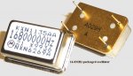
Eclectic: These are mostly just plain crystals- not the packaged crystal oscillator (XO)
HMR: Thanks for that DigiKey link- lots of prospects, but odd ball freqs. abound still!

Prior to freq. synthesis,many radio hams (including myself) were heavy raw crystal users, especially on VHF ~144-148 MHz, and even back in the mid 1960s I used to import from the likes of Jan Crystals, Fort Myers Florida - they're still going! You could specify any freq., & package, cut etc. Things peaked during the mid 1970s CB craze- cheap sets abounded that suited conversions to other freqs. All manner of VXO (Variable Crystal Oscillator) tweaks & circuitry evolved.

I for one really need to make a study of current packaged XOs, freqs. & overtones. Such classics as 3.579545 MHz NTSC TV colour burst are well known (& much used as "engines" elsewhere), but the rationale for that 28.322 MHz offering package escapes me. x3, x5, x7, x9 harmonics don't seem to fall anywhere useful. 3 x 28.322 MHZ = 84.966MHz & thus off the bottom of the FM band. Steve - the producer of that Morse beacon- mentions a 10 yo. 486DX-100 MHz motherboard was the source for his project in fact.

FWIW however, 28.322 MHz is right in the middle of the global 10m ham band global beacon network, & that freq. should hence be avoided for any non ham PICAXE driven transmitters. When propagation conditions suit, 40mW can span oceans with a decent antenna!
 
Last edited:

MPep

Senior Member
Yeah but if you doubled 14.31818MHz, then you'd have a 28MHz frequency that you could use!
 

manuka

Senior Member
MPep- nice thought, but crystal harmonics tend odd (fundamental x3,x5,x7 etc) rather than even. Furthermore the entire 28.0-29.70 MHz RF 10 m band portion is restricted to licenced radio hams, & has been since 1947! Stan (ZL2APS-since 1967)
 

MPep

Senior Member
Manuka - yeah it was a bit of tongue-in-cheek there!! Just 'answering' the previous comment re no 28MHz. Doubling can be done using an (external) EXOR chip, if I recall correctly.
I certainly agree that ODD harmonics are by far the easiest to gather and make use of.
 
Top