Diode Mixing circuit for multiple interrupts

kranenborg

Senior Member
Hi,

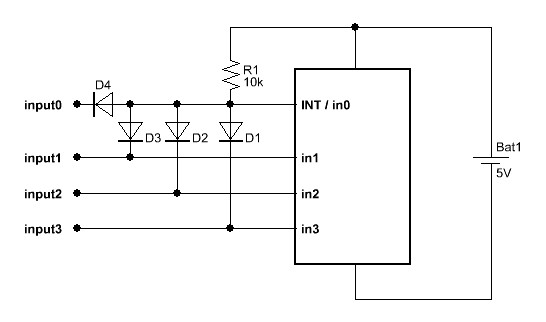
For multiple interrupts (2 or more) that are active LOW, the following circuit should work:


The pullup resistor keeps the INT / in0 input high as long as none of the inputs gets low. Use schottky diodes for a sufficiently low voltage drop across them (I always use BAT85).
Note that due to the orientation of the diodes the inputs are always isolated from each other, so you can connect any output combination to them without any problems. Of course the LOW interrupt signal should be available on the pins long enough to allow detection in the interrupt routine by reading the state of the input pins in order to decide which input actually caused the interrupt.

In case of an active HIGH interrupt, reverse the diodes and have a pull down resistor to GND instead.

Otf course SETINT should be used to properly select the interrupt input port.

Best regards,
Jurjen
www.kranenborg.org/ee/picaxe
 
Last edited:

kranenborg

Senior Member
You may use this interface for serial interrupts too, i.e. use the same line for an interrupt to indicate that a serial message is underway, then send the message itself using SEROUT on the same line. I can recommend reading hippy's excellent tutorial on serial interrupts (which put me on the right track): http://www.hippy.freeserve.co.uk/picaxesi.htm . There is almost no project in which I do not use this concept!

PS1: If you fear that in an application using serial interrupts the serial message received on INT/in0 may get corrupted due to another interrupt incoming on intput1..3, then do not implement input0, i.e. the INT/in0 input is then solely used for generating the interrupt. This of course will cost you an extra pin ...

PS2: Changed the value of the pullup resistor to 10K, the original 1K (default value in my SPLAN drawing program) draws too much and unnecessary current


Regards,

Jurjen
 
Last edited:

unigamer

Member
Well it doesn't work for me but I think I know why. My diode's are not of the type you described and the voltage seems to drop to about 0.5v on the pins so this is not enough for TTL logic to work. I will be ordering more parts soon so I will let you knwo if this solves my problem.
 

BeanieBots

Moderator
Any old diode will do. 1N4148 or BAT85, whatever.
If you are seeing 0.5v, then that is correct. It means one (or more) of your diode OR'd inputs is low.
 

unigamer

Member
I just went with two simple switches. Instant detection wasn't important and it works just as well without interrupts. Thanks for your help because I will use the diagram in the future for the serial interrupts like you suggested.

I am about to post the robot that I am making!
 

kranenborg

Senior Member
I am still a bit confused, was the problem solved or did I make a mistake in the diagram (or was the SETINT setting in your program incorrect, maybe)?

Regards,
Jurjen
 

unigamer

Member
The problem is solved, I just didn't use interrupts. I used normal switches and just checked there status every so often in the code. There may have been a mistake in the diagram but it is more likely my code was wrong. I never actually got to using the SETINT command but instead just detected the switch status and showed them on the debug console. The behaviour of the switches was completely wrong. To get any of them to on then they all had to be pressed down. Any other combination made no change.

Thanks for your help anyway because like I said I will most likely use a similar circuit for serial interrupts eventually.
 
Top