der_fisherman
Member
Hi,
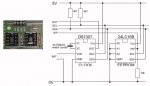
I have been looking around for a complete schematic for this great bit of kit, but other than the "bits & pieces" of schematics in the documentation, I have not been able to find one.
I am guessing, but I cannot believe that the PCB was designed without a full schematic being made first.....so would it be too much to ask to have it made available as a download? (Assuming that I have not simply missed it on my searches! Apologies if I have!!)
Other boards have to my mind better and full information, the 28-PIN PROJECT BOARD for example has a full schematic, which I use each and every time I use that PCB.
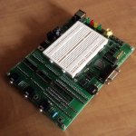
Furthermore, I am going to modify the AXE091 slightly to allow me to socket the resonator, which means I can change it when I wish, as I once did with the 28 Pin Project Board, which works just fine.
This mod is important (I feel) if you own a mixture of chips as I do, different ages, speeds and types and you need higher performance from a newer chip than the AXE091 otherwise allows.....
I just used some turned pin sockets, supplied in strips, that just happen to be the same widths apart as the holes for the resonator in the PCB. They are optically identical with the other sockets on the AXE091 PCB.
Its a simple and effective and very easy change to make. The resonators are sold here on ebay, in pairs for very little money, so you can buy a suitable range for almost any PICAXE chip needed.....
Two methods. 1) Solder sucker, will allow resonator to be removed undamaged and re-used when required. 2) NO solder sucker, cut resonator up and remove each leg singly to reduce the possibility of damage to the PCB.
A little experience with all aspects of soldering is recommended....ask a friend who has the necessary knowledge and experience as well as the tools is better than damaging the unit....
Thanks in advance.
Andy
PS. I just looked at the small schematics again, they do not properly identify the connections on the board either, so for a failure free usage, you need to check everything out with an Ohmmeter and write it down, to make sure you connect correctly.
All in all, the PCB needs to be documented far better....
I have been looking around for a complete schematic for this great bit of kit, but other than the "bits & pieces" of schematics in the documentation, I have not been able to find one.
I am guessing, but I cannot believe that the PCB was designed without a full schematic being made first.....so would it be too much to ask to have it made available as a download? (Assuming that I have not simply missed it on my searches! Apologies if I have!!)
Other boards have to my mind better and full information, the 28-PIN PROJECT BOARD for example has a full schematic, which I use each and every time I use that PCB.
Furthermore, I am going to modify the AXE091 slightly to allow me to socket the resonator, which means I can change it when I wish, as I once did with the 28 Pin Project Board, which works just fine.
This mod is important (I feel) if you own a mixture of chips as I do, different ages, speeds and types and you need higher performance from a newer chip than the AXE091 otherwise allows.....
I just used some turned pin sockets, supplied in strips, that just happen to be the same widths apart as the holes for the resonator in the PCB. They are optically identical with the other sockets on the AXE091 PCB.
Its a simple and effective and very easy change to make. The resonators are sold here on ebay, in pairs for very little money, so you can buy a suitable range for almost any PICAXE chip needed.....
Two methods. 1) Solder sucker, will allow resonator to be removed undamaged and re-used when required. 2) NO solder sucker, cut resonator up and remove each leg singly to reduce the possibility of damage to the PCB.
A little experience with all aspects of soldering is recommended....ask a friend who has the necessary knowledge and experience as well as the tools is better than damaging the unit....
Thanks in advance.
Andy
PS. I just looked at the small schematics again, they do not properly identify the connections on the board either, so for a failure free usage, you need to check everything out with an Ohmmeter and write it down, to make sure you connect correctly.
All in all, the PCB needs to be documented far better....
Last edited:
 )
)