DC motor RPM
- Thread starter Simbad
- Start date
Welcome to the PICAXE forum.
Common ways of doing this are to:
Click here for a forum search.
Common ways of doing this are to:
- Use a striped spinning disc with clear and black areas and a 'light gate' (LED + photodiode) to determine how fast the disc (which will be attached to the motor) is spinning
- Attach a rotary encoder to the motor
Click here for a forum search.
You don't need additional information about the motor, you just need to add some external hardware which is attached to the rotating motor shaft.Can you please explain what is behind measuring RPM with pulse counting?
In this case I need some additional information about the motor?
An example - you make a disc with x equal size black sectors and x transparent sectors the same size as the black ones and these sectors are ordered like this: black clear black clear black clear black clear... You also make a light gate with an LED and photodiode. All these items can be obtained from an old inkjet printer.
Light up the LED, spin the motor and count the pulses from the photodiode. You can determine the RPM from this: RPM = (pulses per second * 60) / number of black segments on disc.
Another way...
If you watch the motor voltage on a CRO, you'll see a back-EMF spike associated with each commutator pad+brush disconnect. Three spikes per REV I think for a normal three pad armature. So just AC amplify this spike signal and count the spikes-per-second. No encoder hardware required, just an op-amp or transistor amplifier.
Theory...
Try monitoring the amplified output from a hall effect device while holding it against the motor in various different positions and attitudes. You may find a position that produces reliable variations related to RPM.
Last edited:
There are a multitude of ways to do it, but I think the opto - interrupter method is probably the easiest and cheapest way to go. These are found in most printers, scanners and CD Rom Drives. The drawing below may be useful.
Attachments
-
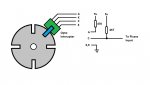 33.2 KB Views: 40
westaust55
Moderator
It might also help if you explain in detail the purpose of your project and the accuracy required.
What shaft speeds will be applied?
What accuracy is required?
physically how big is the motor?
how much room do you have for sensors?
Maybe a photo of the motor is you do not have a datasheet/website link to details of the motor.
If an approximation is all that is required for the speed, the average output voltage fed to a PICAXE ADC input may suffice.
For accurate speed sensing there are optical devices as Goeytex has mentioned or, if the shaft is physically large enough to support a magnet (or two),
a hall effect (magnetic field) device could be used to give 1 (or 2) pulses per revolution.
Then depending upon the shaft speed with optical or magentic either the PULSIN or COUNT command could be used.
"I will spin it to produce voltage" if I read this literally, this tells me you intend to motor/spin this motor, which will become a generator, is that what you meant by this statement?
If so then the speed measurement can be quite straightfoward in that output voltage will be proportional to speed, so you can measure that with a PICAXE ADC.
If so then the speed measurement can be quite straightfoward in that output voltage will be proportional to speed, so you can measure that with a PICAXE ADC.
Thank you for helping.
I found this http://www.soselectronic.com/?str=371&artnum=5840 - Its ok?
Can you please explaine how to measure output voltage from motor when I spin it, its 24v 25w motor and I will spin it to get aroud 10v(and if higher?), tried with drill and it took around 1k rpm for 10v, not sure just approximate
-What accuracy is required?
-not critical, minor discrepancy is not crucial
-physically how big is the motor?
-length 8 cm width 7 cm , its hard to disassemble this motor to look inside for coils and magnets, its monolith-made
-how much room do you have for sensors?
-pretty enough
-"I will spin it to produce voltage" if I read this literally, this tells me you intend to motor/spin this motor, which will become a generator, is that what you meant by this statement?
-yes, I will try to charge 12v 3.2A battery(gel cell) with this motor,additional question what diode should I use to charge on generator + wire .
-no datasheet,found in my garage
To someone with nerves of steel") , explaine me this methode
, explaine me this methode
I found this http://www.soselectronic.com/?str=371&artnum=5840 - Its ok?
Can you please explaine how to measure output voltage from motor when I spin it, its 24v 25w motor and I will spin it to get aroud 10v(and if higher?), tried with drill and it took around 1k rpm for 10v, not sure just approximate
-What accuracy is required?
-not critical, minor discrepancy is not crucial
-physically how big is the motor?
-length 8 cm width 7 cm , its hard to disassemble this motor to look inside for coils and magnets, its monolith-made
-how much room do you have for sensors?
-pretty enough
-"I will spin it to produce voltage" if I read this literally, this tells me you intend to motor/spin this motor, which will become a generator, is that what you meant by this statement?
-yes, I will try to charge 12v 3.2A battery(gel cell) with this motor,additional question what diode should I use to charge on generator + wire .
-no datasheet,found in my garage
To someone with nerves of steel
, explaine me this methodeWill be very grateful if you provide some schematics how to realise this with 18m2, and why do I need to use amplifier, what wave will look with/without amp?If you watch the motor voltage on a CRO, you'll see a back-EMF spike associated with each commutator pad+brush disconnect. Three spikes per REV I think for a normal three pad armature. So just AC amplify this spike signal and count the spikes-per-second. No encoder hardware required, just an op-amp or transistor amplifier.
Last edited:
My suggestion was based upon the mistaken assumption that you were powering the motor, not using it as a generator.
Just measuring the output voltage should be enough, and the easiest method.
How will the motor be turned? Wind/water/handle?
Steppers make far superior generators for low RPM sources.
Just measuring the output voltage should be enough, and the easiest method.
How will the motor be turned? Wind/water/handle?
Steppers make far superior generators for low RPM sources.
Hi,what diode should I use to charge on generator + wire .
Almost any diode which is rated to dissipate a few watts continuously should be suitable (obviously it also needs to be rated for a few amps and tens of volts).
But if you're using the "motor" to charge a battery, then (above a minimum speed) the output voltage will be clamped just above the battery voltage, so not useful to indicate speed.
Similarly, if you can't see the commutator to count the number of segments then you can't use the impulses from that to indicate speed. In any case I think you'd need an oscilloscope to examine the waveform to decide how best to amplify/detect the impulses.
I think one of the direct methods of detecting the shaft rotation would be best. It rather depends what components and tools you have available, or need to buy. The two obvious methods are optical and magnetic. The easiest might be just white and black bars of paint on the shaft, with a LED and a transistor or resistor light sensor. Or magnetically, you could use a hall-effect sensor, a magnetic reed switch (reed relay) or even a magnetic "search" coil (perhaps just detecting a "flat" or "pip" on the motor shaft).
Cheers, Alan.
"But if you're using the "motor" to charge a battery, then (above a minimum speed) the output voltage will be clamped just above the battery voltage, so not useful to indicate speed. "
Good point.
You can get small disk shaped rare-earth magnets that have the polarity split side-to-side, rather than the more common face-to-face. Like a North semicircle and a South semicircle on the same face. A magnet like that could easily be located on either end of the motor spindle and a ratiometric hall effect device would give a nice big wavelike signal when placed face on to the magnet. The wave frequency would be the same as the RPM. It will probably look very much like a sinewave with constant amplitude across the whole RPM range. And no problems with vibration or balance. And a weatherproof robustness hard to achieve with optical methods.