Darlington Array Frustration

Sorry to bother you wonderful people...

I have a Picaxe 28X-2 which I am trying to interface to a ULN2803APG Darlington Array. I want the output of the array to trigger a relay. To test the concept, I created a simple program to flash an LED. Your typical code:

Do
High B.1
Pause 1000
Low B.1
Pause 1000
Loop

The same code used so often. It is loading onto the Picaxe bootstrap, and will flash an LED if placed correctly, so I know it is not a problem with code.

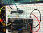
The ULN2803APG is then placed as per the data sheet, with pin 9 connected to ground, and pin 10 connected to +5V.

I have used pin 2 and 17 as the input/output on the Darlington array.

Relay is wired correctly, and works. I can trip the relay by connecting the green wire shown in picture to positive. However, when connected to the Darlington array, nothing happens. The Darlington array will not flash the LED either. (In the position shown, the LED flashes on for a second, and off for a second, as expected. Nothing is changed by removing the LED.)

PicaxeDarlington.jpg

I have two of the 2803APG, as well as a ULN2003, none of which work.

Hopefully I have made an embarrassing newbie mistake - can anyone shed some light please?

Many thanks,

Charles
 

Hansen

Member
1: Do you have a diode over the relay
2: have you try two active input on 2803APG and ULN2003 with 5 volts
 

Janne

Senior Member
Think for a moment how your relay is connected. The ULN2803 will be switching the ground connection. It means when the input of 2803 is low, the output is high impedance ie. not connected anywhere. When the input goes high, the output of the 2803 goes to ground (-the voltage drop of the darlington transistor).. So you need to supply voltage to the other terminal of the relay.

External diode is not required, because 2803 has internal clamp diodes for inductive loads.
 

bgrabowski

Senior Member
Connect the relay to +V and use the darlington to sink the current. Don't forget to use a 1K resistor with your LED.
 

westaust55

Moderator
Hello Charles.

The answer by Janne above is correct.
You need to have a look at the datasheet for the ULN2803A which will help you understand how it works.
http://www.datasheetcatalog.org/datasheets/105/366825_DS.pdf

If you look at page 2 of the datasheet, you can see the collector of the transistor is connected to the "output" pin. The emitter is connected to 0V.
The supply connection to pin 10 is only for the free-wheeling diodes and is not a power supply source to the outputs.
So as Janne advises, when you make the PICAXE output high, the Darlington transistor turns on and acts like a switch conducting to 0V.
Therefore as bgrabowshi has stated, the relay coil needs to be connected between +V and the Darlington "output" pin.

The "free-wheeling" diodes protect the transistors when the transistor is turned off.
At the instant of turn-off, the voltage across the relay coil is reversed and in summation with the supply voltage results in a higher than actual supply voltage is presented at the ULN2803 pins. The diode effectively shorts the relay coil during this voltage reversal to prevent the excessive voltage at the ULN2803 pins.
 
Thanks so much for all of your help, people. That now works.

Newbie mistake, and misreading circuit diagrams for sure.

Picaxe Manual 3 also shows the motor in the diagrammatic description of the darlington array being placed between the output and +5V.

Quite embarrassing, so I thank you for your kindness and patience.

Charles

PS: Normally don't forget a resistor in series with the LED. Just a bit of lazy bread boarding. I should be shot then for posting it on the forum. :)
 

GeorgeC47

Senior Member
I understand what they do - it is the term free-wheeling that puzzles me.
The Wiki article calls them flyback diodes which makes perfect sense.
 

Goeytex

Senior Member
Freewheeling is a throwback term from early mechanical devices, particularly engine / transmission shafts that freewheeled (offered no resistance) when power was removed. With the freewheeling selector turned off when power was removed, the the engine acted as a brake (resistance). With it on, the vehicle would coast ( no resistance)

A freewheeling diode has high resistance in one direction and conducts in the other thus it "freewheels".
 
Last edited:

Reloadron

Senior Member
Freewheeling Diode, Snubber Diode, Flyback Diode and a few other names are used to describe the function of a diode in a circuit. The name is not specific to any particular diode. For example the 1N4XXX series of diodes are frequently used as a freewheeling diodes but would only be called such when used in a specific application. When the same diode is used for example in a full wave bridge someone may look at it and call it a rectifier diode.

A pretty good explenation of the function can be found here in the Wiki. Additionally a Google of Freewheeling Diode, Snubber Diode and Flyback Diode will bring up countless hits explaining the function in detail.

Ron
 

GeorgeC47

Senior Member
I found this explanation -
'I believe the term freewheeling comes from the notion that current is freewheeling, for a short while, in the inductor/diode circuit after the supply voltage is switched off.'

I can see how the analogy of when power is applied to a motor for a while and is then switched off, the motor continues to run as it slows down, ie 'freewheels'. However the analogy breaks down because the motor does not spin in the opposite direction, which is what the current does in an inductive circuit when the emf is removed.
 

Dippy

Moderator
Many devices have changed names over the years and many devices sort of interchange names too e.g. bypass/decouple.

"But surely all diodes fit that description?"
- yes, I guess that's generally true, but sometimes prefixes and suffixes (e.g. "flyback" or "pump") are used to clarify their purpose and job in the circuit. Often it helps you find a device in a large schematic and helps a room-full of grumbing designers get to grips.

My Dad always referred to capacitors as "condensers". Even in the 80's car mechanics would refer to the capacitor by the ignition points as a "condenser". And how about condenser micropohones? Another old hangover which has become 'tradition'.

It sometimes reflects the age and era and background of the contributor :)

I'm afraid you'll just have to get used to it George.

Remember too, that a motor is an inductor and generator...
 

Paix

Senior Member
Very much similar with opto-coupler or opto-isolator. It just depends what your viewpoint is at any given moment, as it's the same component for the most part.
 
Top