Curious resetting of 28X1 without debug

Hydroid

Senior Member
Hi All,

First the disclaimer: While I've been working with servos for 30+ years in R/C aircraft, this is my first attempt to integrate them with picaxe......

I thought that since one of my hobbies is R/C aircraft, and I love clocks, it would be appropriate to construct a clock using servos - with the final product having maybe R/C airplane props as hands to complete the theme.

Anyway, I designed a basic setup with three servos, one for hours, one for '10s' of minutes and the third for minutes.

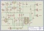
Initially, I had the whole mess on the AXE091 board using the same 5V supply to power everything. I experienced nothing but resets - which I thought might happen given that I know servos are very noisy (electrically). I re-designed my setup on a larger breadboard with twin 7805 regulator based power supplies fed from a dual secondary transformer. One supplies the 1307 RTC and the 28X1picaxe and the other supplies the three servos (diagram attached).

Even with dual supplies, filtering caps and bypass caps on the 1307, the 28X1 and even on the 28X1's reset pin, I still got nothing but resets - evidenced by the three servos executing their start of program sweep test per the code:

Code:
'Servo connections:
'Hours on Out0 (Pin 21)
'10's of minutes on Out1 (Pin 22)
'Minutes on Out2 (Pin 23)
'All servo signal feeds through 330 ohm series resistor.

	wait 2								'wait 2 seconds for settling
	
	
	setfreq m8								'sets operating frequency at power-on
	i2cslave %11010000, i2cslow, i2cbyte			'initiates and sets DS1307 slave address


'Initialize servos							'225 is full CCW, 75 is full CW

	servo 0,210
	servo 1,210
	servo 2,210


'Cycle test servos clockwise


	b0 = 10								'step delay (Max 255)

	for b1 = 218 to 97 step - 1
	
		servopos 0, b1
		
		pause b0

	next


	for b2 = 220 to 110 step -1
	
		servopos 1, b2
		
		pause b0
		
	next


	for b3 = 220 to 103 step - 1
	
		servopos 2, b3
		
		pause b0
		
	next


'Return servos to home position


	for b3 = 103 to 220
	
		servopos 2, b3
		
		pause b0
		
	next
	

	for b2 = 110 to 220
	
		servopos 1, b2
		
		pause b0
		
	next
	
	
	for b1 = 97 to 218
	
		servopos 0, b1
		
		pause b0
		
	next
	
	
	wait 2								'if delay is <2, then picaxe continually resets
										'and debug screen never populates (remains blank)
	'wait 1								'delay can be wait 1 and pause 1000 - as long as
	'pause 1000								'it totals 2 or more seconds
	
	
	b3 = 60								'ensure b3 can't be same as b1
		

'Read RTC

read_rtc:

	readi2c 0, (b0, b1, b2)						'reads RTC values (sec, min & hrs)
	
	
	debug									'resets occur if debug remarked out ??
	
		
	pause 500 
	
	if b3 = b1 then
	
		goto read_rtc
		
	endif


'Set hands

	gosub conv_hrs
	
	servopos 0, b12


	gosub conv_ten_min
	
	servopos 1, b13


	gosub conv_min
		
	servopos 2, b14


	b3 = b1


	goto read_rtc	


'Convert Hours

conv_hrs:

	b10 = b2 and %00010000 / 16					'set b10 to the number of 10's hours (bit4)
	b11 = b2 and %00001111						'set b11 to the number of 1's hours
	
	b12 = b10 * 10
	b12 = b12 + b11 - 1						'-1 since hours scale starts at 1 not 0
	
	b12 = b12 * 11
	
	b12 = 218 - b12

return


'Convert 10's Minutes

conv_ten_min:

	b13 = b1 / 16
	
	b13 = b13 * 22
	
	b13 = 220 - b13

return


'Convert Minutes

conv_min:

	b14 = b1 and %00001111
	
	b14 = b14 * 13
	
	b14 = 220 - b14

return
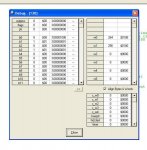
I tried a few things and came upon my particular solution quite by accident. If I put a 2 second (or more) delay after the inital servo sweep test AND a debug statement just after the readi2c line, the clock works perfectly and does not reset. If I shorten the delay to anything less than two seconds OR remove / remark-out the debug statement, it will continually reset. When it resets, it also resets ALL the DS1307 registers (see attached screenshot of debug screen)

Looking in the manual under the servo command I see reference to not being unable to use the servo command at the same time as timer or pwmout/hpwm. I'm not using these - unless timer is somehow a part of pause or wait ??

I get the same result whether the servos are connected or not. I've physically disconnected the three servos and it still resets.

As long as I have the 2 sec or longer delay and the debug statement, the clock works flawlessly even after I disconnect the pogramming cable. I've let it run for hours beside me while I'm on the computer and t never resets once....

Any thoughts because I'm stumped :confused:

Regards, John.
 

Attachments

Last edited:

Janne

Senior Member
Hi,

Not sure if it has to do with the problem, but the manual suggests the servo's only working correctly at 4MHz clock. And your program runs at 8... Worth a try, i think.
 

Hydroid

Senior Member
Better !

Not sure if it has to do with the problem, but the manual suggests the servo's only working correctly at 4MHz clock. And your program runs at 8... Worth a try, i think.
Hmm,

Totally missed that line in the servo functions section of the manual. 28X1 can run at 4MHz or 16 MHz.... No other frequency will work correctly

Thanks !

Removing the setfreq m8 so that it operates at the default 4 MHz has solved part of the problem.

I can now remove the post sweep test pause completely and it is stable.

Removing the post RTC read debug however, still results in resets :confused:

One other thing that happened is that it totally changed the positioning of the servos. The first run @ 4MHz almost twisted the arms off the servos as it greatly changed their positions. My span used to be in the ~220-100 range. I've had to change that to ~110-50 range now.

Seeing as the manual also recommends keeping in the 75 to 225 range, I'll have to remove the servo arms, rotate and reattach them. then recalibrate the code to get them into the recommended range again.

Guess it wouldn't be any fun if it worked right the first time anyway... :rolleyes:

Well, it's a start. Thanks.

John.
 

westaust55

Moderator
At 8MHz, timing intervals are half those at 4MHz for most commands.

Thus 220-100 at 8MHz equates to 110-50 range at 4MHz.

While the 75 to 255 value sin the manual are a fair starting point, they are not set in concrete and you dio need to experiment.

I have SERVOs that just do not move if the pulse duration is out of the valid range but other SERVOs will try to go past limits and may be damaged.
Try starting with a narrow band around 150 and broading the band to find the min and max pulse duration values that your SERVO can properly work over.
 

lanternfish

Senior Member
Hi

Have you tried running the program without the servos connected (and debug remarked out)? You will need some way of monitoring the servo outputs to check they are operating correctly.

What happens if you put a pause instead of debug?
 

Hydroid

Senior Member
At 8MHz, timing intervals are half those at 4MHz for most commands. Thus 220-100 at 8MHz equates to 110-50 range at 4MHz..... Try starting with a narrow band around 150 and broading the band to find the min and max pulse duration values that your SERVO can properly work over.
Makes sense, thanks.

Hi, Have you tried running the program without the servos connected (and debug remarked out)? You will need some way of monitoring the servo outputs to check they are operating correctly. What happens if you put a pause instead of debug?
O.K., tried a few combinations:

Hooked up my scope to monitor one of the servo signals and physically removed the servos from the circuit.

1. With debug remarked out, resets occurred repeatedly - as seen by the servo pulse width changing during the sweep test at the start of the code. After about 5 resets, the DS1307 was affected also as seen by the LED connected to its pin7 going solid instead of flashing at 1 Hz.

2. With debug remarked out and the existing pause 500 increased to pause 2000, resets began to occur after about 5 seconds or so and continued. Again, saw the DS1307 affected (same as above)

3. With debug still remarked out, increased the pause 500 to pause 5000. This resulted in stable operation for about 40 seconds (no evidence of pulse width change on the scope), but then resets began to occur.

I can leave the debug statement in there - it works that way - but it would be nice to understand why it has to be there :confused:

It seems like overkill to use a 28X1 in this design. I have a few 18X chips and am going to try that. Have to see if the same problem remains.

Regards, John.
 

Technical

Technical Support
Staff member
This implies an hardware issue with ground connections etc. Does taking the download cable out of the socket make a difference? What happens with batteries instead of your power supplies?

Debug should make no difference, it is just a time delay during which the serout pin is 'pulsed'. The fact that it does make a difference really only implies a hardware issue somewhere.
 

Hydroid

Senior Member
This implies an hardware issue with ground connections etc. Does taking the download cable out of the socket make a difference? What happens with batteries instead of your power supplies?
Removing the programming cable makes no difference.

I removed ALL the power supply components and ran the circuit from two sets of 3AA batteries in series - so that the 1307 & the picaxe were on one 4.5V supply, and the servos were on the other (remembering to connect the -ve's together). NO difference. If the debug statement is remarked out, it doesn't work. If it's there, all is good.

Debug should make no difference, it is just a time delay during which the serout pin is 'pulsed'. The fact that it does make a difference really only implies a hardware issue somewhere.
I don't know what it could be. The servos work fine during the initial sweep test, the trouble only starts after the RTC values are read in and converted then sent to the servos.

I've seen a servo clock in the projects area that runs off the mains as the timing source - counting pulses to set the 'hands'. Has anyone actually made a clock using servos with the RTC as the time source ?

I have no problem admitting it's my fault - I just don't know what the fault is :)

Regards, John.
 

hippy

Ex-Staff (retired)
I don't know if this is relevant but the diode bridges for the inputs to the voltage regulators are wrong.
 

Hydroid

Senior Member
Schematic fixed

I don't know if this is relevant but the diode bridges for the inputs to the voltage regulators are wrong.
Good spot Hippy. They would do something horrible to the supplies if actually wired like that!
Whoa ! That would be a mess....:eek:

No, they're not actually attached like that - My noob skills with Picaxe VSM schematic layout. A quick 90 degree CCW rotation and re-attachment fixed that. Luckily, the actual part is imprinted with a + mark on it.

Thanks for pointing that out. Schematic updated.
 

Hydroid

Senior Member
A few more experiments

So I tried a few more things over the last bit...

1. Rebuilt the clock using a picaxe 18X instead of the 28X1, just to see what would hapen. Absolutely no difference - except it took a long time to get the coding right with a limited number of variables compared to the 28X1. It still works great with the debug statement, but craps out without it. (This is true if I run the setup from dual battery sets as well)

2. Installed an 08M to supply the 18X with a pulse every minute and recoded it to count those pulses to keep time:

08M code:

Code:
# picaxe 08M

#rem

- 60 Hz conditioned signal fed to in1 (pin6)
- out4 (pin3) delivers a 100ms pulse every minute

#endrem

low 4 

w0=0

main:

pulsin 1,1,w3				'measure pin 1 pulse width

if w3 < 600 then main			'loop if short pulse (noise)

inc w0

if w0>3599 then				'next 3 lines count 60 +ve half-waves of AC,
	pulsout 4, 10000			'generates a 100 ms pulse on out0 and resets counter back to 0
	w0=0
endif

goto main
18X code:

Code:
# picaxe 18X

'08M delivers a 100ms pulse to input 7
'decreasing value moves servos clock-wise


	i2cslave %11010000, i2cslow, i2cbyte	'initiates and sets DS1307 slave address
	
	wait 2						'wait 2 seconds for settling


init:

	servo 5, 164
	servo 6, 174
	servo 7, 171


'Cycle test servos clockwise


	b0 = 10						'step delay (Max 255)


	for b1 = 164 to 96 step - 1
	
		servopos 5, b1
		
		pause b0

	next
	

	for b2 = 174 to 117 step -1
	
		servopos 6, b2
		
		pause b0
		
	next
	

	for b3 = 171 to 108 step - 1
	
		servopos 7, b3
		
		pause b0
		
	next
	

'Return servos to home position


	for b3 = 108 to 171
	
		servopos 7, b3
		
		pause b0
		
	next
	

	for b2 = 117 to 174
	
		servopos 6, b2
		
		pause b0
		
	next
	

	for b1 = 96 to 164
	
		servopos 5, b1
		
		pause b0
		
	next


	i2cread 0, (b0, b1, b2)				'read in sec, min & hrs from RTC
	
	wait 2						'wait 2 seconds for settling


'Calculate Minutes


	b0 = b1 and %00001111				'set b0 to current minutes


'Calculate 10's Minutes


	b1 = b1 / 16					'set b1 to current 10's of minutes


'Calculate Hours


	b3 = b2 and %00010000 * 10			'RTC set for 12hr time, so isolates bit4 (10's hrs)
	b4 = b2 and %00001111
	
	b2 = b3 + b4					'set b2 to current hours
	
	if b2 = 12 then					'if hours = 12, reset to 0 as zero on scale
		b2 = 0					'represents 12 O'Clock
	endif 


	setint %10000000,%10000000			'set interupt for in7 to monitor for 08M's pulse


main:

	if b0 > 9 then					'increment routines:
		inc b1					'b0 is minutes
		b0 = 0
	endif
	
	if b1 > 5 then					'b1 is 10's of minutes
		inc b2
		b1 = 0
	endif
	
	if b2 > 11 then					'b2 is hours
		b2 = 0
	endif
	
	
	b5 = b2 * 6						'multiply current hr by divison increment	
	b5 = 164 - b5					'subtract from zero pos'n
	servopos 5, b5					'position hours servo
	
	b6 = b1 * 11					'same as above, but for 10's of minute servo
	b6 = 174 - b6
	servopos 6, b6
	
	b7 = b0 * 7						'same as above, but for minutes servo
	b7 = 171 - b7
	servopos 7, b7
	
	pause 500
	
	goto main
	
	
interrupt:

	if pin7 = 1 then interrupt			'wait until in7 is low
	inc b0						'increment b0 by 1
	setint %10000000,%10000000			're-enable interupt
	return
It only uses the RTC to set the initial hand (servo) positions. So far (it's been almost six hours now) it's working great - Not one reset, not one glitch. Only thing is it's losing time, but I believe that I know where that is from. I believe I'm missing some pulses from the 'mains' in the time it takes for the 08M to issue its 100 ms pulse to the 18X. I'm working on that....

So, it appears that for some reason, that my clock is unhappy if I read the RTC within a loop for servo positioning unless there is a debug statement there :confused:
 
Last edited:
Top