Correct syntax - 08M2 and stepper

ZOR

Senior Member
Am I right in thinking B should be C when using an 08M2?

dirsB =%11111111

pinsB= %00010000 ?
pause delay
etc


I have tried it and my stepper does not move just makes a vibrational pulsing noise' Just want to get this confirmed before poking around further. Thanks

EDIT: Just realised the binary numbers also wrong for the 08M2
 
Last edited:

bfgstew

Senior Member
Yes it should be C, dirsC = %00010111

pin 3 is an input only so you will have to use pin 0, so need to disconnect to get your 4 outputs.
 

ZOR

Senior Member
Many thanks. I am stumbling with a bipolar motor driven by/into 08M2 and L293D. Not use to 2 coils (double lines of binary, presumably for each coil)

So for an 08M2 this is all wrong? How does one work this out?

Code:
pinsC= %00010000 :pause delay 
pinsC= %00011000 :pause delay
 
pinsC= %00001000 :pause delay
pinsC= %00001100 :pause delay
 
pinsC= %00000100 :pause delay
pinsC= %00000110 :pause delay
 
pinsC= %00000010 :pause delay
pinsC= %00010010 :pause delay
 

bfgstew

Senior Member
Not being awkward ZOR, but have a read of the tutorial by Westaus55 in a previous thread, it gives some code example to run a bipolar through a L293 via Picaxe, all you have to do is change the pins to suit your 08M2 from the 18M2 in the tutorial, you'll have it running in no time...........;)
 

ZOR

Senior Member
Many thanks, sorry I was pointed there before but XMAS with a mother in law in the house forced me to erase the last days in my memory. Regards
 

Goeytex

Senior Member
In the code above, you are still attempting to use pin3. (C.3)

As bgfstew indicated above, Pin3 is an input only and will not respond to pinsC. So with the 08M2 you will need to use the serout pin ( Pin0) as an output) and skip over bit 3 n the dirsC / PinC commands.

Try this:

Code:
let dirsc = %00010111 
        
main:
        let pinsc = %00010010	'step 1
	pause delay
	let pinsc = %00010001	'step2
	pause delay
	let pinsc = %00000101	'step 3
	pause delay
	let pinsc = %00000110	'step 4
	pause delay
goto main                           'loop forever
 
Last edited:

ZOR

Senior Member
Thanks Goeytex. I have looked at other examples but they all take me down the road of lookups.

I am trying to keep my code as it is but do not understand how the 4 pairs of code get used. Yes that line of code is wrong (C.3)

I am using C.0, C.1, C.2, C.4

Each two lines (pairs of code (Binary) how do they relate to the 4 pins of the 08M2 being used.

Code:
pinsC= %00010000 :pause delay = C.4
pinsC= %00011000 :pause delay = C.3 & C.4
 
pinsC= %00001000 :pause delay = C.3
pinsC= %00001100 :pause delay = C.2 & C.3
 
pinsC= %00000100 :pause delay = C.2
pinsC= %00000110 :pause delay = C.1 & C.2
 
pinsC= %00000010 :pause delay = C.1
pinsC= %00010010 :pause delay = C.1 & C.4
If my understanding above is correct, then I can understand why this would be wrong for the 08M2.
If I knew what the correct C.X combinations would be for an 08M2 then I might then be able to work it out for myself, ?
 

bfgstew

Senior Member
ZOR, have you tried the example by Goeytex? It should work and is not using lookup, it is a simple loop that energizes the coils in the correct sequence. I think yours is stalling the motor as it is not in the correct sequence, try it and see, then if it works, you can expand your code to suit.
 

ZOR

Senior Member
Thanks bfgstew, I did not see Goeytex code appear while I was writing back. However I tried it but the motor still just sings. I have tried combinations of leads etc but no movement. Maybe the motor is a faulty one (Ebay/chinese)

However thanks both very much, will get another motor and try that. Regards
 

bfgstew

Senior Member
Before you throw the towel in, check you have the 4 outputs working as they should, I think you may have pin 0 still as part of the download circuit, this does need to be physically disconnected from it before it can be used as an output pin.
 

ZOR

Senior Member
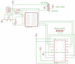
Thanks again, I used this circuit

08M2STEPPERCIRCUIT.jpg

I have used 0.1 headers for linking changes, so I know my serial pins are definately broken/connected

The 4 outputs go into the L293D IC
 

bfgstew

Senior Member
I think you need to double check everything here ZOR, you state you are using a Bipolar stepper motor and a L293 driver for it, but your schematic is showing a ULN2803 and a unipolar stepper motor???????????? The ULN2803 will not drive a Bipolar but will a Unipolar, what have you got exactly?
 

ZOR

Senior Member
Thanks. As I ended I said my 4 Picaxe outputs were going into a L293D, sorry if I was not clear I had found the circuit and was using the 08M2 part of the circuit but using a L293D to drive the bipolar
 

rossko57

Senior Member
Well, your actual circuit is still a secret. I think we can now tell which output pins you are using from the Picaxe ... but we have no idea how you have connected those to the L293D, nor how you have connected your motor to that in turn. Not possible to tell you how to sequence it without that information.

If its buzzing, the motor is probably ok.

The delay you are using is important, and that is still a secret too.
 

bfgstew

Senior Member
If you are using the L293, then it should look something like this
bipolar-schematic.png
(this is using the 18M2) so need to change the outputs to suit the 08M2
 

ZOR

Senior Member
Thanks again. Using an 08M2 it's more than just outputs to configure. I am switching over the serial pins to get my 4 outputs into the L293D. The L293D circuit is the same as yours, which I took from Manual 3.

I tried another bipolar stepper motor, different to the one earlier, and that jitters backwards and forwards slightly.

I am going to slug my circuit with long delays, and will put LED's on outputs so I can try and see whats happening. I will break off today and get back to it in the morning. Thanks again
 

oracacle

Senior Member
sound like you dont have the motors wire wound the correct way. make sure you have each coil connected to just one side of the L293, if it jitters swap the wires on on one coil (eg 14 and 11), stepper motors come with a certain amount of trial and error
 

ZOR

Senior Member
Many thanks. I have got things half working.
I disconnected my Picaxe board from the L293D board, and wired LED's to each output leg to see what order they were pulsing out. The output was random and went silent when I put my finger on the top of the Picaxe.

I cleared the code from the Picaxe and it showed none of what I took as instability. I reloaded the Picaxe, moved my jumpers back so I had a fourth output for the motor, and to allow C.5 to be used as an input. It was unstable again, but I found by accident that if I put the C.5 link back (C.5 to 22k) my outputs pulsed perfectly and I had no instability when putting my finger back on top of the Picaxe, I had omitted a 4.7k resistor to ground R5 on circuit.

So now the motor I had substituted started rotating! That rotates so slowly, took me a while to see it moved.

Hopefully that's it. Will go back and play with pause etc. But thanks to all that helped me.

VERO.jpg
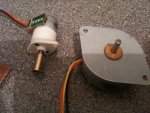
The offending open C.5 link


The smaller motor was the one I was trying to evaluate, the larger showed me there was now life
MOTORS.jpg
 

bfgstew

Senior Member
Good to hear you have made progress ZOR.

If you are using the code Goeytex provided you need to have the pause time set to pauseus like thus.

Code:
let dirsc = %00010111 
        
main:
        let pinsc = %00010010	'step 1
	pauseus 200	
        let pinsc = %00010001	'step2
	pauseus 200	
        let pinsc = %00000101	'step 3
	pauseus 200	
        let pinsc = %00000110	'step 4
	pauseus 200
          goto main                           'loop forever
Adjusting the 200 value lower will increase rotational speed but it may cause the motor to stall, in that case increase it until you get a nice steady speed, needs a bit of trial and error to find the correct speed.
 

SAborn

Senior Member
When using Pin C.5 as an input, you did use a "disconnect" statement in your program first before using it as a input pin, didnt you???

I cant see any of your full code posted or any mention of using C.5 so it a little hard to tell what you have done.
 

ZOR

Senior Member
Thanks Saborn. I put a schematic up on #12. It was a circuit I had found and was using. It shows C.5 being patchable to be an input, having R5 to keep it on the ground when nothing inputted.

As far as whats done, it's all there around the 08M2, until taking the 4 output legs C.0,C.1,C.2 and C.4 into an LM293D using manual 3 circuit (into marked Pin 4, Pin 5, Pin 6, in 7)

I did not draw a complete circuit as I was only wanting to try a stepper out.

Edit: Also not having done any real code yet for the motor/electronics, I presumed by manually/mechanically breaking C.5 I did not need disconnect? or do I?

Thanks again
 

SAborn

Senior Member
I presumed by manually/mechanically breaking C.5 I did not need disconnect? or do I?
Think about it, what is C.5 as a default pin?
Its serial in, so without a "disconnect" every time C.5 changes state the picaxe thinks its a download happening, and shuts down waiting for a new program download.

Now if you use a disconnect and not a "reconnect" in program, then to download a new program you will need to do a Hard Reset upon loading a new program.
 

ZOR

Senior Member
Thanks SAborn. I never came accross any reprograming issues each time, maybe because I powered off each time I reset link positions? Anyway many thanks for the information, and being sensible as suggested I will adopt "disconnect" and "reconnect" in future code. Regards
 

SAborn

Senior Member
Because i dont always follow threads, i will suggest a different aproach to consider after you master the circuit you have.

This was a circuit i done some years back for a 08m, and which uses the enable pins.

Here is a cut and paste of the code example to suit, also showing direction changes below.

Code:
symbol step_counter = 	w0

symbol speed =		50


	high 			0,1
	low 			2,4


Main:

	toggle 1,2
	toggle 0,4
	inc step_counter
	pause speed
	toggle 0,4
	inc step_counter
	Pause speed
	
	goto main
	
	
'%%%%%%% example of direction changes below %%%%%%%%%%%%%

	
'%%%%%% FORWARD STEPPING %%%%%%%%%%%%%%%%%%%%%%%%%%%%%%%%
	
	toggle 0,4
	pause speed
		
'%%%%%%%%% REVERSE STEPPING %%%%%%%%%%%%%%%%%%%%%%%%%%%%%	
		
	toggle 0,4
	toggle 1,2
	pause speed
I dont suggest you change your circuit, get the one you have working first then try different methods.


08M stepper driver.JPG
 

ZOR

Senior Member
Many thanks. Now I have proved my motor will suit the job it's over to building/finding mechanical bits, then I will get back to controlling it and will play around with your suggestions. I had not come across the ENA (presume enable) pin of the L293, not shown in manual 3 picture.
 

oracacle

Senior Member
Many thanks. Now I have proved my motor will suit the job it's over to building/finding mechanical bits, then I will get back to controlling it and will play around with your suggestions. I had not come across the ENA (presume enable) pin of the L293, not shown in manual 3 picture.

out of interest what are you building?
 

ZOR

Senior Member
Thanks SAborn for the datasheet link. Suppose I was being a bit lazy just taking manual 3 circuit, which doesn't name enable pins.

Hi oraccacle, I was looking for very small steppers to make a pan/tilt assembly to carry a CCTV board camera to mount in a garden globe light. So at this stage trying to find and test motors on their suitability as well as finding small mechanical linkage/mounting parts.

Now that I have working basic driver boards for both Unipolar and Bipolar steppers I can test other motors. Regards
 

oracacle

Senior Member
fair enough, do you plan on trying to mount the camera around their centre of gravity, otherwise i can see there being issue with there lack of strangth.

the larger of the 2 you posted ealier looks to be froma scanner and will only produce maybe 0.004n/m of torque - something like 4 gram/cm. they are normally quite heavily geared while in the scanner and are moving very little weight over a very smooth suface. and controller by very nice controllers
 

ZOR

Senior Member
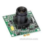
The cameras used are board cameras, so the torque required is very very small.

CAMERA.jpg

I have been building camera units to put around the house, after being burgled a while back. A DVR records 24 hours. I use garden halogen floodlights for cases, obviously stripping out light fittings. I think the cases are coming to an end now as the stores B&Q etc want to sell the more expensive LED lights which have sealant around the front glass so that you cannot open them!

Regards
 

eclectic

Moderator

ZOR

Senior Member
Thanks eclectic, I bought out the last few from Homebase in Reading who told me they were getting rid of stock. Another DIY store in Reading called Wickes also gave me same story. They also told me Toolstation was a Wickes company, so maybe they are pushing them their way. Anyway thanks for info, they make excellent cases for what I am doing, but do need a bit more care on sealing the elements as I think they are only IP44 rating.
The other article was interesting too, thanks. Best wishes New Year
 
Top