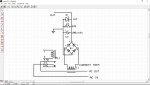
Here is a diagram of the current transformer setup I plan to use. I haven't tested it yetHi,
Firstly, you say the load is "a.c." and you are using a current transformer (but the same would probably apply to a Hall-effect sensor) which will produce a 50Hz alternating voltage signal. How are you converting that to a "low" input voltage level on each of the PICaxe pins?
The basic sequencing is quite simple, but you might need to set some lower "timeout" limits, to ensure that each load is driven for a sufficiently long time.
However, your "timer" input may require some degree of "multi-tasking" capability, i.e. two or more pins must be monitored "at the same time" (depending whether the shut-down must occur "immediately" when c.5 from the timer goes low). There are at least three ways to do that : 1) You can ensure that each part of the program has a "polling loop" which continuously checks the levels of the required input pins rapidly in sequence. Or 2) an Interrupt could be used, or 3) , as you're using an M2 PICaxe, you could use its multi-tasking capability (which uses two or more "Start" labels). There should be an explanation in the User Manuals, but the Command Reference is probably a place to start.
Cheers, Alan.
I also wonder if I cannot parallel 4 of this circuits and use only one sense input that will be high while any relay is on and goes low when its load switch off. Then the output must go to the next pin till all 4 is done and start to loop
Another way I can try is to use some logic chip that triggers on a falling edge and invert signal so I get a high to the sense input. Will have to look into it
Attachments
-
 323.9 KB Views: 11