Chook-House-Control-Redesign

manie

Senior Member
Everything that Hippy + Dippy + BB + BCJ + Dr.A + Manuka + Andrew + Peter + JGlenn and all the other gurus have said actually showed up. It's a HOSTILE environment there and one needs to design for it. The first unit worked fine but was prone to damage from spikes etc. There is an electric fence energiser in close proximity and the 220V AC pans out to be 243-251 V AC !, so....

Digital inputs and outputs : How best to protect them ?
1.
+5V signal-->R-->C--0V ?
2.
+5V signal-->4N28/35 opto-->28x1 pin ?

The analogue signals from the LM35DZ's seems quite OK as I have followed the datasheet and de-coupled the +5V supply as well as R-->C-->0V from the signal line. This seems to work fine with 100nF caps.

Please may I have your suggestions and thoughts.
 

manuka

Senior Member
THAT ELECTRIC FENCE MAY BE ONE THING, but I'd first want to know more about these mains spikes before suggesting 220V ideas. Are you in -say- a lightning prone region ? Have you considered running the lot off a solar PV? Have you considered -gasp- total relocation?
 

manie

Senior Member
You never cease to amaze me ! Let me tell you about the 12V PB/Charger/Energiser....

After doing ALL sorts of shielding/de-coupling etc. there was still this spike, and I mean SPIKE ! Touching the 5V supply to the temperature sensors (both DS18B20's and LM35DZ's) woke me up !:eek: It turned out to be the energiser charging/discharging INTO the 12V car battery and this off course ended up in the circuit. Moving to a separate 7AH 12V battery cured that problem and temp's were reporting just dandy...:) the circuit started closing/opening the 12V coil relays just fine. Now this farmer has a HEAVY industrial background, so he did not want the relays to power the small 12V winch motors (10A under "good" load) and supplied me with REALLY HEAVY DUTY contactors:confused:. These however had 220V coils so......... 220V to the relay contacts (which were operating really well without switching anything...) to switch the contactors In/Out, to switch the 10A 12V winches On/Off....(not my idea, remember my other thread ????).

Now up to that point I thought I was ahead, MAN was I wrong ! The first relay switched 220V to the first contacter coil, the first contactor pulled in with a LOUD "CLACK !!!", and then..., well this is the new thread about re-design:eek:.

Needless to say, I have since convinced the farmer that he knows more about chickens than contactors and load switching so the contactors will GO AWAY ! I will use relays to switch the 12V winches on/off (I'll double the relays in parallel if it makes him feel better), I am using wildly de-coupled 28x1 project boards, Ive re-designed the Input/Output boards (separate this time) using 4N28/35 opto IC's on the digital inputs etc. etc. So, with the knowledge that I've removed (probably) the spike inducing problems, what ADDITIONAL protection do you guys suggest....?

Just after you've stopped laughing your a.....s off for me !

Edit:
Stan, the one thing you were really worried about, the electric fence and the RF modules.... those were the ONLY ones working as planned, FAULTLESSLY ! Now go explain that... just shows what amazing things.........
 
Last edited:

manie

Senior Member
Relacate ? Where ? The chook-house is there, the fence for it is there for a VERY S.A'n reason, I think the site is fairly fixed Stan.

Edit
And I mean this is chook-HOUSE, not coop.... real pro'. Can't move.
 

Dippy

Moderator
Rules.

1. Good sensible design based on skill, calculation and experience.
2. Doing tests before finalising design. These tests include PSU noise, ambient RFI/EMI, electrical noise/spikes caused by downstream components and switching.
3. Using PROPER components suitable for the job and NOT some hairy old cra* that is in the back of the drawer.
4. Doing it ON-THE-CHEAP is NOT always ideal.
5. Doing it on the cheap can work out more expensive in time and money .... oh, I think you've discovered this now :)

If you can't do any of the above then consider a job in ice-cream sales ;)
 

Dippy

Moderator
Oh PS.
In answer to your question, opto-isolating is safest in terms of isolation.

But all this depends on what is being induced onto the 'signal' line.
Remember if everything is high impedance then the induced noise appears bigger.
In many cases you can shunt that noise down to ground with appropriate caps.
i.e. you provide a lower impedance route for noise etc.

It really is up to YOU to do some measurements and also physical screening or moving of cables.
You've had a zillion suggestions on possible methods. What more can we do when we can't see it? (Polite answer appreciated :) )
 

BeanieBots

Moderator
Dippy has covered most of it.
In such situations, it often comes down to overall layout which comes from experience and is hard to describe. The subtlties don't show up in a circuit diagram.

Some of the power rail spikes may well be caused by a desulphation unit on the Pb as well as the fence electronics.

Have a read of some the "PICAXE in car" threads. Many of the tips will be applicable in your situation.

If you can't relocate, then you will need to shield and decouple.
Don't forget that extra decoupling is not achieved by using bigger caps, it is achieved by using more of them (in decade values) and in the right places. A badly placed one can actually make things worse!
 

cvrwy

Member
Manie......
Panasonic produces a line of devices called "ZNR" Transient/Surge Absorbers. They look like a small ceramic disc capacitor. Digi-Key stocks them here in the states. I've added them across all the inputs, to ground, on one of my PCB projects. The boards were part of a signal system used on an outdoor model railroad. As I was ready to check out my boards, we had to dismantle the railroad to prepare for a move, so I cannot tell you if they would work for you. I never set up my boards.

One that I chose for my 12vdc power input is at this link......
http://search.digikey.com/scripts/DkSearch/dksus.dll?Detail&name=P7282-ND
 

Andrew Cowan

Senior Member
Ah, you mean Varistors (I think).

These conduct when above a certain voltage, thus abosorbing and disipating spikes.

Last one that I saw was in a 110V battery charger. There was a varistor, then a fuse. A friend had plauuged the charger into 240V, the varistor had turned on, and it had shorted the mains, blowing the fuse and protecting the rest of the charger.

A
 

Dippy

Moderator
Andrew, 'varistor' is the generalised name for this type of device and Panasonic call their own product "Transient/Surge Absorbers" - just to clear that up.

Very useful devices as long as the user reads and understands the Data Sheet specifications. And, once again, like Zeners etc. they are NOT magic on-off devices.
 

Andrew Cowan

Senior Member
True - when searching for a replacement for the friend, I found they have rather cloudy turn on voltages, rather than 65v fully off, 65.5v fully on. Not that you need that to absorb spikes.

A
 

Dippy

Moderator
Not sure about 'cloudy'?

I guess they perform as they say in the Data Sheet.
The new ones designed by Paul Xenon are on/off over a 0.001V delta-V.
 

manie

Senior Member
That is all good info - Thanks people. For now, I'll go with what I know a little more about which are Resistor-Zener + caps in the power regulator side.

Those Panasonic data sheets looks confusing to me. It seems that the higher the clamping voltage the higher the Amps rating.... can't read them yet.

As far as decoupling the LM35's are concerned, that is working well, done it according to datasheet circuit. I am putting in Ultra Fast clamping diodes across the relay coils and have added some 100nF caps as well. I think I should add R-C across the relay contacts just to try and reduce sparking (if any ?) across them when starting/stopping the motor.

As for the RS-232 between 28x1's and RF, I'll go with a "master" which will act as "arbitrator" between the other chips. At least I've got 3x 4096K memory available now....
 

manie

Senior Member
Well, I made progress again. The project is now using two 28x1's, one as "Master Controller" and the second as "watchdog" and LCD controller. With 4096K memory in each chip I thought it will be enough. it was. JUST !

The Master uses 3.3K for controlling the IO's and calculations and decisions. The LCD controller handles the human interface, menus/keypad etc. as well as a small "watchdog" function. From other posts in other threads you already know that I got the HserIn/Out running OK. The back and forth comms was tricky at some places to ensure timing is OK and that each chip can react to stimulus from the other. I found that different pause periods were required depending on what function was requested by whichever chip. It works now.

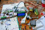
I am doing bench-testing as "messy" as possible. Right next to the (cheap) "hi/low-fi" and the TV with the cell phone in between from similar mains (on a farm here) as at the actual site (farmer starts/stops pumps etc.). So far looks OK. I will take the o'scope along when installing to see if I can learn more on-site.

I will also be mounting the whole thing in a nice steel electrical DB board type wall box which should provide some good "Faraday" goodies. This will be well GROUNDED, to Terra Firma and 0V to that. Should provide better protection than that which I had previously when mounted in an EXPENSIVE plastic box.

To show "messy" testing here is a pic.
 

Attachments

manuka

Senior Member
Manie: I think you must have sent the wrong picture-that's far too tidy. It'd barely rate a 1:10 on the international "Dad's shed" 10 point messy workbench scale. Even the creative delight below is only considered ~7:10 by purists!

In belated response to Dippy I humbly offer a personal 5:10 (with dead Flymo endorsement) that my wife regularly awards me. Stan.
 

Attachments

Last edited:

Dippy

Moderator
I thought it was one of Stan's piccies :)
(Not fellow Kiwi Andrew "Brightsparks" - which are very pretty).
 

manie

Senior Member
Stan you are SOOOOOO lucky ! Taht i so tidy and neat, I'm borrowing space on the wife's table runner, so imagine dropping some solder there !!!!
 

manie

Senior Member
A good terminal program please ! I need to send example: byte 30, byte 10 byte 11 byte 1 via Hserout for Hserin(background), data must arrive together in scratchpad for decoding. SuperTerm, AIterm cant do. I also need to send two bytes eg. 20(fixed code) and xx(variable value), how can do please ?
 

hippy

Ex-Staff (retired)
A good terminal program please ! I need to send example: byte 30, byte 10 byte 11 byte 1 via Hserout for Hserin(background)
I presume you mean use a Terminal Emulator to simulate a PICAXE sending data to another PICAXE using HSERIN.

data must arrive together in scratchpad for decoding
Impossible - All characters and data bytes are sent sequentially so will be received in scratchpad one after the other.

AIterm cant do.
Sure it can.

Disconnect the serial cable.
Tick "Send Whole Lines"
Tick "Local Echo".
Type "30,10,11,1" into the bottom text area.
Click on the "#" button next to "Send".
Display will show "«1E»«0A»«0B»«01»" - The hex values of what was sent.

Un-Tick "Local Echo".
Connect serial cable.
Click on "#"
Bytes will be sent down the serial cable.

I also need to send two bytes eg. 20(fixed code) and xx(variable value), how can do please ?
As above, enter "20,xx", click on "#".
 
Last edited:

manie

Senior Member
Hippy: Thanks for the answer, I've done that prior to reading your post, including "local echo" etc. still no Interrupt. Here is the scenario:
PC--terminal program--Axe027 cable--433MHZ RF module<><>433MHz RF module--MAX232--Hserin pin 7(28x1)
The above Hserin is on the same "bus" as the Hserout from 2nd 28x1 to the above receiving 28x1-Hserin. From the 2nd Axe the Interrupt occurs just fine with background receive. From the RF--MAX232 input I don't enter into the interrupt routine at all.

I have just tried doing it with a spare 28x1 project board. Max232 on breadboard with LED's showing signal both on INPUT from 433MHz and output from Max232.

433MHz out--Max232 input--Max232 out---|--1K--LED---0V
|
------28x1 Hserin (pin7)
EDIT:
(prints incorrect,shift 28x1 input underneath 1K--LED etc)

Max232 output sits high(5v) with no output from RF module, and the LED on its output dies when it goes low, the RF output goes high.

I have tried both Setintflags flag5 and Setint 0,1 and Setint 1,1. Interrupt is not triggered.

Any help welcome, thanks.
 
Last edited:

hippy

Ex-Staff (retired)
PC--terminal program--Axe027 cable--433MHZ RF module<><>433MHz RF module--MAX232--Hserin pin 7(28x1)

Take the 433MHz and MAX232 out of the configuration, adjust HSERSETUP for correct polarity, and try that. If necessary run a small test program on the 28X1 to tell if anything is being received. Try just pulling the serial in line up and down by hand and use a simple program to see if interrupts are being detected or not.

However, having gone back through two pages of postings I've no idea what SETINT's or anything else has to do with things. Advice can only be given with context and I don't have the time to trawl through other forum posts when going off at a tangent.

I'd suggest starting a new thread, describe the problem, what it should do, what it does do, what it doesn't do, include a code listing; preferably simple so others can replicate what you have and demonstrate the problem.
 

hippy

Ex-Staff (retired)
Try this ... Disconnect whatever else is on TX and RX ( legs 17 and 18 ) of the 28X1, connect leg 17 to leg 18 and you should see an interrupt ocuring every second ...

#Picaxe 28X1
#No_Data
#No_Table

HSerSetup B9600_8,%001

SetIntFlags %00100000, %00100000

Do
Pause 1000
HSerOut 0, ( "X" )
Pause 10
Loop

Interrupt:
SerTxd( "Interrupt " )
hSerFlag = 0
SetIntFlags %00100000, %00100000
Return
 

hippy

Ex-Staff (retired)
Then try ...

#Picaxe 28X1
#No_Data
#No_Table

HSerSetup B9600_8,%001

SetIntFlags %00100000, %00100000

Do
Pause 1000
HSerOut 0,( 30, 11 ) : Pause 10
HSerOut 0,( 10, 1 ) : Pause 10
Loop

Interrupt:
Do While ptr <> hSerPtr
Get ptr, b0
ptr = ptr + 1
SerTxd( #b0, " ")
If b0 = 1 Then
SerTxd( CR, LF )
End If
Loop
hSerFlag = 0
SetIntFlags %00100000, %00100000
Return
 

manie

Senior Member
Hippy: Thanks, I will juggle some more.
#Picaxe 28X1
#No_Data
#No_Table

HSerSetup B9600_8,%001
The above is for the X2 yes ? Does things change when you DO have EEPROM/TABLE data ? (As far as the Hserial commands are concerned)

My test code:
Code:
'test program - 433MHZ module-->Max232-->28x1
'Hserin interrupt

setfreq m8
pause 10
hsersetup B9600_8,%01
hserptr=100
hserflag=0
setintflags %00100000,%00100000

Main:

	b0=0
	do
	pause 500
	sertxd("main")
	pause 500
	loop
	

Interrupt:

pause 2000

sertxd("In Int")

get 100,b0:get 101,b1
select case b0
	case 0
		sertxd("Only 0")
	case >0
		if b1>=10 then
			for b3=1 to b1
				high 7
				pause 1000
				low 7
			next b3
		end if
		if b1<10 then
			b1=b1*1000
				high 7
				pause b1
				low 7
		end if
end select


hserptr=100
hserflag=0
setintflags %00100000,%00100000

sertxd("Exit Int")

return
I will add a rough schematic later.
 
Last edited:

hippy

Ex-Staff (retired)
#Picaxe 28X1
#No_Data
#No_Table

HSerSetup B9600_8,%001
The above is for the X2 yes ?
No, 28X1, hence "#Picaxe 28X1" ;-)

Does things change when you DO have EEPROM/TABLE data ? (As far as the Hserial commands are concerned)
No. It simply avoids waiting for any data or table to download, of which neither are used by the program.


Connect leg 17 to leg 18 as before and add hserout 0,("X") after the Sertxd("main"). That generates interrupts for me.
 
Last edited:

manie

Senior Member
Hippy: I was refering to the "HSerSetup B9600_8,%001 " part.

sorry if I sound tedious, but I really don't have the basics of serial yet. Google just turms up mostly rubbish and if one does not understand the the "T" and "N" parts and which idles high or low then you cannot really fathom out the problem never mind the cause. Thanks for your input this late (01h17 here), appreciated.
EDIT:
this is the CHOOK-house project, the chicks are having a nap, I suggest we follow suit.....
 
Last edited:

hippy

Ex-Staff (retired)
Ah right; I've got into the habit of always specifying the three bits for HSERSETUP even through not all bits are implemented on the X1 parts ...

% <RX Invert> <TX Invert> <Background Receive>
 
Top