Andrew Cowan
Senior Member
Hi all.
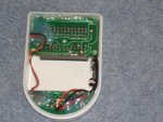
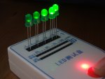
I recently bought an LED tester (from ebay). It is mainly for working out what colour superbrights are, but also for working out what current LEDS need.
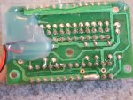
I was dubious about how accurate the current provided would be, so I ran opened it up to see how it works. Answer - resistors. Not suprising given its cost.
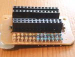
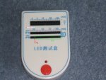
Anyway, it seems very odd - here are the values of the resistors, and the calculated current (given a voltage drop of 2V from a 9V battery), at each test current:
2mA slot: 1540 ohms, so 4.5mA
5mA slot: 364 ohms, so 19mA
10mA slot: 364 ohms, so 19mA
20mA slot: 364 ohms, so 19mA
30mA slot: 240 ohms, so 29mA
I have no idea why these values are so wrong, but I plan to replace the resistors. There were also several solder bridges in the unit - I have cleaned these up now.
So anyway, I will replace the 2ma, 5mA and 10mA slot resistors - with 3.5K, 1.4K and 700 ohm resistors. Is 2V an average value to assume for the voltage drop?
Has anyone any idea why the manufacturer has done this?
Andrew
EDIT:
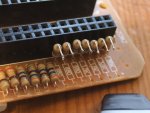
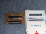
Upon looking at the PCB further, the bottom strip (for common anode LEDs), has very odd wiring. Going from left to right (looking from above the unit):
Pin 1: 364 ohm resistor to 0V
Pin 2: 9V
Pin 3: There is space for a 360 ohm resistor to 0V, but instead, there is a solder bridge to pin 4 (0V)
Pins 4-13: 0V
Weird!
The row above (for common anode LEDs) also has odd wiring:
20mA slot:
Pin 1: 364 ohm resistor to 9V
Pin 2: 0V
Pin 3: 364 ohm reistor to 9V
50mA slot:
Pin 4: N/C
Pin 5: 120 ohm resistor to 9V
Pin 6: N/C, but i assume it should go to 0V
Pin 7: Linked to pin 5
70mA slot:
Pin 8: Linked to pin 10
Pin 9: N/C, but i assume it should go to 0V
Pin 10: 120 ohm resistor to 9V
150mA slot:
Pin 11: 51 ogm resistor to 9V
Pin 12: N/C, but i assume it should go to 0V
Pin 13: linked to pin 11
I recently bought an LED tester (from ebay). It is mainly for working out what colour superbrights are, but also for working out what current LEDS need.
I was dubious about how accurate the current provided would be, so I ran opened it up to see how it works. Answer - resistors. Not suprising given its cost.
Anyway, it seems very odd - here are the values of the resistors, and the calculated current (given a voltage drop of 2V from a 9V battery), at each test current:
2mA slot: 1540 ohms, so 4.5mA
5mA slot: 364 ohms, so 19mA
10mA slot: 364 ohms, so 19mA
20mA slot: 364 ohms, so 19mA
30mA slot: 240 ohms, so 29mA
I have no idea why these values are so wrong, but I plan to replace the resistors. There were also several solder bridges in the unit - I have cleaned these up now.
So anyway, I will replace the 2ma, 5mA and 10mA slot resistors - with 3.5K, 1.4K and 700 ohm resistors. Is 2V an average value to assume for the voltage drop?
Has anyone any idea why the manufacturer has done this?
Andrew
EDIT:
Upon looking at the PCB further, the bottom strip (for common anode LEDs), has very odd wiring. Going from left to right (looking from above the unit):
Pin 1: 364 ohm resistor to 0V
Pin 2: 9V
Pin 3: There is space for a 360 ohm resistor to 0V, but instead, there is a solder bridge to pin 4 (0V)
Pins 4-13: 0V
Weird!
The row above (for common anode LEDs) also has odd wiring:
20mA slot:
Pin 1: 364 ohm resistor to 9V
Pin 2: 0V
Pin 3: 364 ohm reistor to 9V
50mA slot:
Pin 4: N/C
Pin 5: 120 ohm resistor to 9V
Pin 6: N/C, but i assume it should go to 0V
Pin 7: Linked to pin 5
70mA slot:
Pin 8: Linked to pin 10
Pin 9: N/C, but i assume it should go to 0V
Pin 10: 120 ohm resistor to 9V
150mA slot:
Pin 11: 51 ogm resistor to 9V
Pin 12: N/C, but i assume it should go to 0V
Pin 13: linked to pin 11
Attachments
-
 730.9 KB Views: 57
 -
 306.4 KB Views: 28
Last edited: