Cellar pump with wireless control

syntony

Member
Hello all,

I have a project to my house,
when it's rainning too much, water comes to my cellar, I need to pull out the water, I make a vertical drain, I put the pump and sensors inside
PICAXE give a solution, It's a project without claim
I find a solution, that's one solution, it's not the best!
but, for me, it's enough

I use PICAXE 18, because after, I want to improve the project

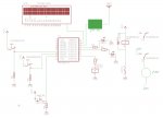
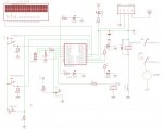
I have a pump with 2 water sensors:
one for Low level, the second for High level
and a switch for manual mode (pump=ON during 3 minutes)
when water arrive, the Low level is ON:
- I start a timer
- If the High sensor is ON before end of timer, pump= ON
and wait low sensor=OFF, pump=OFF
- if the high sensor is OFF and the timer is over, pump=ON
and wait low sensor=OFF, pump=OFF

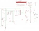
informations send to a Transmitter (TX-4MAVSA10 AUREL)
and arrive on a receiver ( RX-AM4SF -AUREL)
the second PICAXE, give informations to 3 LED
0ne for Low level, one for High level, one when PUMP=ON


to improve the range, I work now on a repeater with TRXQ1-433
and also with a receiver with RSSI information

Anybody can give remarks on my project

I'm a newbie in PICAXE, I use only few code


Syntony
 

Attachments

manuka

Senior Member
Shades of "The Sorcerer's Apprentice" ! How about a circuit diagram & some pictures?! This sounds a lot of fun, but don't forget to factor in fail safe, prolonged rainfall, power cuts & standby power supplies. What rating is the pump ? I'd also be wary of important 433 MHz data being corrupted over longer ranges, especially if local interference may be an issue. Things can happen VERY quickly with basement flooding of course, so it needs to be bullet proof !

Stan
 

Attachments

syntony

Member
Yes, Manuka, y're right...
I agree with you..

I don't make a schematic now, but I can
it's very simple, only PICAXE and connection

it's difficult to forecast what will happen, but I try

sensor water need to be protected with wire netting
I choose a pump witch can pull off 12000 L/h, 220V AC
also, It's depend of the depth of the vertical drain

I can safe the power supply of picaxe
but not for the pump !! (I don't need to use a backup power supply for 220V AC)
in case of big thunderstorm, sometime, no more energy in the house
but nether for a long time
pratically, water arrive slowly in the cellar,....NOT LIKE YOUR PICTURE !!!! I'm lucky!
so, I have always time to pull off the water
but it's necessary

one time we have a big thunderstorm,
we need to start the pump every 4 hours

for the wireless problem, I know
I want to use FM modules to reduce interference
use good external antenna...
but it's only a control, not a remote control of the pump
 

MPep

Senior Member
Hi Syntony,

Yes you must have a resistor from SerIn to GND. This is also stated in the manuals.
To future-proof your project, I would suggest that you include a download socket anyway (with both resistors).
This way more features can be added without having to remove the chip.
 

syntony

Member
Hi Syntony,

Yes you must have a resistor from SerIn to GND. This is also stated in the manuals.
To future-proof your project, I would suggest that you include a download socket anyway (with both resistors).
This way more features can be added without having to remove the chip.
OK,

I 've draw a new schematic
 

Attachments

Last edited:

hippy

Ex-Staff (retired)
@ syntony : Looks good. The only thing I'd add is 100nF decoupling capacitors and maybe a LED+R to indicate power is on, and another LED+R from Output 0 so you know when the opto has been activated and should have switched the relay and pump on. That helps diagnose problems if the pump isn't working when it should be. If the LED is on the PICAXE has told the motor to be on, if it isn't it's likely a hardware fault, not your PICAXE software which is faulty.

Maybe another LED+R on the transmitter input so you can tell when the PICAXE is sending something out.
 

syntony

Member
@ syntony : Looks good. The only thing I'd add is 100nF decoupling capacitors and maybe a LED+R to indicate power is on, and another LED+R from Output 0 so you know when the opto has been activated and should have switched the relay and pump on. That helps diagnose problems if the pump isn't working when it should be. If the LED is on the PICAXE has told the motor to be on, if it isn't it's likely a hardware fault, not your PICAXE software which is faulty.

Maybe another LED+R on the transmitter input so you can tell when the PICAXE is sending something out.
Hi, Hippy,

I modify schematic and soft like that
sure it's better to exploit the possibilities of the 18X

syntony
 

Attachments

hippy

Ex-Staff (retired)
sure it's better to exploit the possibilities of the 18X

Not always. A LED connected to a line which should have a voltage on it shows that it does have a voltage on it. A LED controlled by software shows the same line should have a voltage on it but there's no way of proving the voltage is there or not without getting a DMM out.

If the LED goes on, but the pump doesn't run you don't know if the software is behaving properly - it may have lit the LED but not set the voltage line. If connected to the actual line you know the PICAXE has put a voltage out. Additionally a LED connected to the actual voltage line will flicker and show various brightnesses which can also be a useful diagnostic in some cases.

It also saves an extra I/O line, although that is not be important in this project.

What's also common is to fit both LED's, say for transmitting; a software controlled LED which lights during the full transmission sequence, a hardware LED which flickers and shows the actual data line activity. The end-user gets a nice clean on-off visual display, the real diagnostics which 'look chaotic' are hidden away.

It's like if an OS puts up a message saying "Copying files..." and seems to wait forever. You don't know if it is or isn't, but looking at the disk light tells you if there is any activity or not.
 
Last edited:

syntony

Member
sure it's better to exploit the possibilities of the 18X

Not always. A LED connected to a line which should have a voltage on it shows that it does have a voltage on it. A LED controlled by software shows the same line should have a voltage on it but there's no way of proving the voltage is there or not without getting a DMM out.

If the LED goes on, but the pump doesn't run you don't know if the software is behaving properly - it may have lit the LED but not set the voltage line. If connected to the actual line you know the PICAXE has put a voltage out. Additionally a LED connected to the actual voltage line will flicker and show various brightnesses which can also be a useful diagnostic in some cases.

It also saves an extra I/O line, although that is not be important in this project.

What's also common is to fit both LED's, say for transmitting; a software controlled LED which lights during the full transmission sequence, a hardware LED which flickers and shows the actual data line activity. The end-user gets a nice clean on-off visual display, the real diagnostics which 'look chaotic' are hidden away.

It's like if an OS puts up a message saying "Copying files..." and seems to wait forever. You don't know if it is or isn't, but looking at the disk light tells you if there is any activity or not.
Yes, my project is not totaly perfect
it's not for use with 100 % of security

we have to understand than if the soft can lit the control LED , it's not sure than OUTPUT for transmitter or OPTO is actived....(In my choice of this project)
so, I can put another sensor to the pump relay,they are free switch, to test the relay
or a current sensor in power line of the pump, or a pressure sensor in the pipe
like that, we can increase the security..
but, for this project, it's not necessary
i't for me, it's under my responsability
it's not for a commercial item

but, y're right, it's important to clarify this...
 

hippy

Ex-Staff (retired)
I certainly agree, it's not necessary to add anything, and entirely redundant when everyting is working as expected. It's more about considering what could be done to help things in the future if something stops working, circuit diagrams and source code having long been lost or filed away 'somewhere'. LED's and R are a cheap way to get lots of information very easily which may save a lot of time later on. They're easy to design into a layout even if not physically fitted on the PCB when first assembled.

One thing which would be worth considering having is a switch across the opto which enables the relay to switch the pump relay on. As long as VCC and mains is there you can activate the pump even if all else fails. An alternative, more fail-safe option, would be physical mains switching so the pump is either controlled by the PICAXE system or manually. Nothing worse than having a pump in place but not working due to some failure when it's needed.
 

syntony

Member
I don't know if PICAXE are reliable, I think so
and the power supply ?, other component ?

when we built a security system like that,
we need to know until where the system can work
evaluate the limit of the system
but we can't manage all, we only approach of 100% of reliable without reach it..

totally secure can be too much expensive

yes, I can put a switch in the pump relay circuit
to cancel PICAXE system in case of out of order

but you put your finger on a point of security, it's very interesting

I just think to upgrade the system...with a test sequence
another PICAXE (eg 08X) every X hours, switch ON INPUT of this 18X, via relay or opto
......I want to built this, just for the fun
 

hippy

Ex-Staff (retired)
Yes, PICAXE are reliable. And agree again, 100% reliability is not cheap nor easy and not usually possible. Costs grow staggeringly as one approaches 100%

I understand you want to build this or fun, but it will play an important role, more so if you come to be reliant upon it.
 
Top