radiogareth
Senior Member
Here's an interesting project....
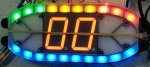
After seeing the MPH (dual 7 segment) display in my Mazda RX8 dashboard my son (who is building a Haynes Roadster, a 'Caterham 7' style car) has decided he would like the same sort of thing in his so is planning a digital dashboard. So my initial thoughts are use a M2 part to measure the pulses provided by the gearbox output shaft (2 per revolution, already a nice 5 volt square wave).
The Mazda display seems to update at around the 0.5 to 0.7 seconds rate - faster and the digits all turns into a blur and slower is, well, slower......
I've spreadsheeted all the figures allowing for gear ratios, diff ratio and tyre size and I get the following 'pulses pre second' figures as minimum (6 Hz at 700 rpm in first gear) and maximum (244 Hz at 6,000 in overdrive).
I'm planning on using the count command (possibly at elevated clock speed to get a decent count at slow speeds) and then the 'Case' command to output a suitable 2*4 bit code to a pair of 4511 BCD-7 Segment driver chips.
Might there be a better way of doing this? A theoretical string of 0 to 130 MPH 'select Var' and then 'case Var to Var' might take a while, even at SetFreq M32.
Thoughts welcome........
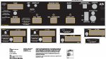
") Nice dash btw, my son Josh has already designed the housing and front panel, a combination of 3-D printed back with compartments and a laser cut/etched reverse overlay.
Nice dash btw, my son Josh has already designed the housing and front panel, a combination of 3-D printed back with compartments and a laser cut/etched reverse overlay.