"Calibrating" LDR using a separate "ambient" LDR
- Thread starter danners430
- Start date
danners430
Member
ooooh! Now that I didn't know! I just assumed from previous experience that pre-processor and compiler directives shouldn't be mixed... even more optimization possible then....If you have
(for example),Code:#DEFINE number 21
then you can write
Code:SYMBOL LoopCount = number - 1 for i = 1 to LoopCount
With the new knowledge from Aries as above, that definitely makes more senseWhy is your set of "#IF"s better than this?
loopend=number min 1 max 26-1 ' limit 0-25
for i=0 to loopend

hippy
Ex-Staff (retired)
I have to agree. It's probably just lack of advanced programming experience which is holding danners430 back from that.Much of the code is repetitive, varying only variables and pin numbers. You could probably combine multiple instances of similar code into a single instance in a loop
Having monolithic source code isn't a problem if that works. But it could be compacted to something fairly simple without losing understandability.
This is my, untested, take on it ...
Code:
#Picaxe 20X2
#No_Data

Symbol I2C_DEVICE_ADDRESS = %01010010 ; $A2

#Define NUMBER 11

; Sensor input pin definitions

Table  1, ( B.0 )
Table  2, ( B.1 )
Table  3, ( B.2 )
Table  4, ( B.3 )
Table  5, ( B.4 )
Table  6, ( B.5 )
Table  7, ( B.6 )
Table  8, ( C.7 )
Table  9, ( C.3 )
Table 10, ( C.2 )
Table 11, ( C.1 )

; Addresses used in Scratchpad

; I2cRead $00, (b0)	Status of LDR #1
; I2cRead $01, (b0)	Status of LDR #2
; etc
; I2cRead $18, (b1,b0)	Dark bits, bit0 = LDR#1
; I2cRead $20, (b0)	Raw ADC of LDR #1
; I2cRead $30, (b0)	Average of LDR #1

Symbol ADR_STATUS    = $00 ; $00-$17 24 bytes
Symbol ADR_DARK_BITS = $18 ; $18-$19  1 word
Symbol ADR_RAW       = $20 ; $20-$2A 11 bytes
Symbol ADR_AVERAGE   = $30 ; $30-$3A 11 bytes
Symbol ADR_TOTAL     = $40 ; $40-$5B 11 words

; Scratchpad access macros

#Define ReadByte(n,adr,var)           ptr = n - 1     + adr : var = @ptr
#Define SaveByte(n,adr,var)           ptr = n - 1     + adr : @ptr = var
#Define ReadWord(n,adr,varMsb,varLsb) ptr = n - 1 * 2 + adr : varLsb = @ptrInc : varMsb = @ptr
#Define SaveWord(n,adr,varMsb,varLsb) ptr = n - 1 * 2 + adr : @ptrInc = varLsb : @ptr = varMsb

; Variables used

Symbol reserveW0     = w0 ; b1:b0
Symbol darkBits      = w1 ; b3:b2
Symbol darkBits.lsb  = b2
Symbol darkBits.msb  = b3
Symbol samples       = w2 ; b5:b4
Symbol total         = w3 ; b7:b6
Symbol total.lsb     = b6
Symbol total.msb     = b7
Symbol n             = b8
Symbol pinNumber     = b9
Symbol adc           = b10
Symbol average       = b11
Symbol darkLevel     = b12
Symbol bitMask       = b13
Symbol status        = b14

; Program code

PowerOnReset:
  Hi2cSetup I2CSLAVE, I2C_DEVICE_ADDRESS

MainLoop:
  Do
    samples = samples + 1 Max 256
    For n = 1 To NUMBER
      ReadTable n, pinNumber
      ReadAdc pinNumber, adc
      SaveByte( n, ADR_RAW, adc )
      Gosub UpdateAverage
      Gosub UpdateStatus
    Next
  Loop

UpdateAverage:
  ReadWord( n, ADR_TOTAL, total.msb, total.lsb )
  ReadByte( n, ADR_AVERAGE, average )
  If samples = 256 Then
    total   = total - average + adc
    average = total.msb
  Else
    total   = total + adc
    average = total / samples
  End If
  SaveWord( n, ADR_TOTAL, total.msb, total.lsb )
  SaveByte( n, ADR_AVERAGE, average )
  Return

UpdateStatus:
  darkLevel = 80 * average / 100
  bitMask = 1 << n >> 1
  If average < darklevel Then
    darkBits = darkBits | bitMask  ; Set Bit
    status   = %01000011           ; Occupied
  Else
    darkBits = darkBits &/ bitMask ; Clear Bit
    status   = %01000010           ; Clear
  End If
  SaveWord( 1, ADR_DARK_BITS, darkBits.msb, darkBits.lsb )
  SaveByte( n, ADR_STATUS, status )
  Return
lbenson
Senior Member
Now +there+ is a masterclass lesson--#define constants, #define macros, TABLE definitions, scratchpad usage, indirection with @ptr, meaningful symbolic names, array handling, and more.it could be compacted to something fairly simple without losing understandability.
Last edited:
danners430
Member
Well, it's taken me until today to finally get my head around it, but I've finally understood the code... (whoever invented the common cold has a lot to answer for!)
I'm assuming that the four #DEFINE statements in lines 39-42 could easily be re-written as a multi-line macro for readability (just by splitting the statements separated by colons into separate lines and changing the directives to #MACRO / #ENDMACRO)?
Also, just to clear up my confusion... I thought readADC had to use the ADC number given on the datasheet instead of the pin number in port.pin format? Or can it use either or?
One thing's for certain though... I'm going to be saving that for future reference - as Ibenson said, that really is a masterclass in advanced PICAXE BASIC...
lbenson
Senior Member
Good catch. As someone (probably hippy) pointed out to me years ago, you can use, for instance, READADC B.1,result in your program because the preprocessor recognizes your intention and puts the right code in. However, if you use B5=B.1: READADC B5,result, the preprocessor can't read your mind to understand that B5 holds the standard pin number rather than the ADC pin number. So you must use the ADC pin number when using a variable.Also, just to clear up my confusion... I thought readADC had to use the ADC number given on the datasheet instead of the pin number in port.pin format? Or can it use either or?
(If I have misunderstood this, or mis-applied it, someone please correct me. (And is there a programmatic way to get "ADC pin number of B.1"?))
danners430
Member
Theoretically, the simple fix would be to replace the pin numbers with the ADC numbers in the Table at the beginning of the program - and for clarity comment the pin number beside it. Mind you, it does compile and simulate on PE6...Good catch. As someone (probably hippy) pointed out to me years ago, you can use, for instance, READADC B.1,result in your program because the preprocessor recognizes your intention and puts the right code in. However, if you use B5=B.1: READADC B5,result, the preprocessor can't read your mind to understand that B5 holds the standard pin number rather than the ADC pin number. So you must use the ADC pin number when using a variable.
(If I have misunderstood this, or mis-applied it, someone please correct me. (And is there a programmatic way to get "ADC pin number of B.1"?))
hippy
Ex-Staff (retired)
Yes, the #DEFINE can be rewritten as multi-line #MACRO blocks, without any effect on the functionality.I'm assuming that the four #DEFINE statements in lines 39-42 could easily be re-written as a multi-line macro for readability (just by splitting the statements separated by colons into separate lines and changing the directives to #MACRO / #ENDMACRO)?
Readability is in the eye of the beholder. I started with #MACRO but then changed to #DEFINE as being more readable IMO.
You can use either directly with the READADC commands, but only when used directly. If a number is loaded into a variable which is used in a READADC command that must be the channel number. For example, on the 20X2 ...Also, just to clear up my confusion... I thought readADC had to use the ADC number given on the datasheet instead of the pin number in port.pin format? Or can it use either or?
Code:
b0 = B.3
ReadAdc b0, b1 ; Reads ADC3, which is on leg C.7
Code:
;      .---------------- Light sensor number
;      |     .---------- ADC channel number
;      |     |      .--- ADC pin  name
;      |     |      |
Table  1, (  1 ) ; B.0
Table  2, (  2 ) ; B.1
Table  3, (  4 ) ; B.2
Table  4, (  5 ) ; B.3
Table  5, (  8 ) ; B.4
Table  6, ( 10 ) ; B.5
Table  7, ( 11 ) ; B.6
Table  8, (  3 ) ; C.7
Table  9, (  7 ) ; C.3
Table 10, (  8 ) ; C.2
Table 11, ( 9 ) ; C.1danners430
Member
Yet it compiles and simulates correctly without change...So I guess that is a bug in my code through oversight; the pin names used in the DATA definitions should be ADC channel numbers rather than pin names.
 Methinks this bug might be a butterfly...
lbenson
Senior Member
I find that when stepping through in simulation with a 20X2, on the first READADC it totally locks up PE6, requiring it to be terminated with Task Manager. Presumably, this is because the first adc command, which is effectively READADC 0,adc, is trying to read a non-existent ADC pin, ADC0.Yet it compiles and simulates correctly without change
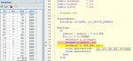
If I replace the table entries as per hippy's post (changing B.4 from 8 to 6), I find it does simulate correctly (stepping through all 11 READADCs once), returning the ADC values for each ADC pin as shown below.
Last edited:
danners430
Member
so... I wonder what happens if you load it onto a chip...? Unfortunately I can't test it just now...
UPDATE: ran the simulation again, and can confirm that stepping through crashes the simulator - not PE6 itself, you can still scroll etc. but the simulation side of things is stuck... Trying to close normally prompts PE6 to get angry and complain that you can't close while simulating... It did, however, work when I didn't step through - just let it run
UPDATE: ran the simulation again, and can confirm that stepping through crashes the simulator - not PE6 itself, you can still scroll etc. but the simulation side of things is stuck... Trying to close normally prompts PE6 to get angry and complain that you can't close while simulating... It did, however, work when I didn't step through - just let it run
lbenson
Senior Member
I believe (as modified with the new table values), it would run as expected--but I also don't have a convenient way to get 11 distinct ADC values (though I wonder what you would get if the pins are just floating).so... I wonder what happens if you load it onto a chip...? Unfortunately I can't test it just now...
danners430
Member
Aye, with the updated table values it runs perfectly fine in the simulator too... Just (morbidly) curious to see what the "old" code would do!I believe (as modified with the new table values), it would run as expected--but I also don't have a convenient way to get 11 distinct ADC values (though I wonder what you would get if the pins are just floating).
lbenson
Senior Member
As it turns out, the "old" code +will+ work on a 20M2 (as far as the READADCs go) because on the M2 parts, the pin number is the same as the ADC pin number. But everything using PTR won't work, because scratchpad is not available on the M2s--however the code could be rewritten to use bptr and upper RAM.Just (morbidly) curious to see what the "old" code would do!
The ADC part of this will run in simulation for either 20X2 or 20M2 if the proper directive is used.
Code:
' 20masterclass ' hippy's from https://picaxeforum.co.uk/threads/calibrating-ldr-using-a-separate-ambient-ldr.31720
'#Picaxe 20X2
#Picaxe 20M2
#terminal 4800
#No_Data
'#define px20X2

Symbol I2C_DEVICE_ADDRESS = %01010010 ; $A2

#Define NUMBER 11

; Sensor input pin definitions

;      .---------------- Light sensor number
;      |     .---------- ADC channel number
;      |     |      .--- ADC pin  name
;      |     |      |
#ifdef px20X2
Table  1, (  1 ) ; B.0
Table  2, (  2 ) ; B.1
Table  3, (  4 ) ; B.2
Table  4, (  5 ) ; B.3
Table  5, (  6 ) ; B.4
Table  6, ( 10 ) ; B.5
Table  7, ( 11 ) ; B.6
Table  8, (  3 ) ; C.7
Table  9, (  7 ) ; C.3
Table 10, (  8 ) ; C.2
Table 11, (  9 ) ; C.1
#else
Table  1, ( B.0 )
Table  2, ( B.1 )
Table  3, ( B.2 )
Table  4, ( B.3 )
Table  5, ( B.4 )
Table  6, ( B.5 )
Table  7, ( B.6 )
Table  8, ( C.7 )
Table  9, ( C.3 )
Table 10, ( C.2 )
Table 11, ( C.1 )
#endif

; Addresses used in Scratchpad

; I2cRead $00, (b0)    Status of LDR #1
; I2cRead $01, (b0)    Status of LDR #2
; etc
; I2cRead $18, (b1,b0)    Dark bits, bit0 = LDR#1
; I2cRead $20, (b0)    Raw ADC of LDR #1
; I2cRead $30, (b0)    Average of LDR #1

Symbol ADR_STATUS    = $00 ; $00-$17 24 bytes
Symbol ADR_DARK_BITS = $18 ; $18-$19  1 word
Symbol ADR_RAW       = $20 ; $20-$2A 11 bytes
Symbol ADR_AVERAGE   = $30 ; $30-$3A 11 bytes
Symbol ADR_TOTAL     = $40 ; $40-$5B 11 words

; Scratchpad access macros

#Define ReadByte(n,adr,var)           ptr = n - 1     + adr : var = @ptr
#Define SaveByte(n,adr,var)           ptr = n - 1     + adr : @ptr = var
#Define ReadWord(n,adr,varMsb,varLsb) ptr = n - 1 * 2 + adr : varLsb = @ptrInc : varMsb = @ptr
#Define SaveWord(n,adr,varMsb,varLsb) ptr = n - 1 * 2 + adr : @ptrInc = varLsb : @ptr = varMsb

; Variables used

Symbol reserveW0     = w0 ; b1:b0
Symbol darkBits      = w1 ; b3:b2
Symbol darkBits.lsb  = b2
Symbol darkBits.msb  = b3
Symbol samples       = w2 ; b5:b4
Symbol total         = w3 ; b7:b6
Symbol total.lsb     = b6
Symbol total.msb     = b7
Symbol n             = b8
Symbol pinNumber     = b9
Symbol adc           = b10
Symbol average       = b11
Symbol darkLevel     = b12
Symbol bitMask       = b13
Symbol status        = b14

; Program code

PowerOnReset:
#ifdef px20X2
  Hi2cSetup I2CSLAVE, I2C_DEVICE_ADDRESS
#endif

MainLoop:
  Do
    samples = samples + 1 Max 256
    For n = 1 To NUMBER
      ReadTable n, pinNumber
      ReadAdc pinNumber, adc
      sertxd(#pinNumber,"-",#adc," ")
#ifdef px20X2
      SaveByte( n, ADR_RAW, adc )
#endif
      Gosub UpdateAverage
      Gosub UpdateStatus
    Next
    sertxd(cr,lf)
  Loop

UpdateAverage:
#ifdef px20X2
  ReadWord( n, ADR_TOTAL, total.msb, total.lsb )
  ReadByte( n, ADR_AVERAGE, average )
  If samples = 256 Then
    total   = total - average + adc
    average = total.msb
  Else
    total   = total + adc
    average = total / samples
  End If
  SaveWord( n, ADR_TOTAL, total.msb, total.lsb )
  SaveByte( n, ADR_AVERAGE, average )
#endif
  Return

UpdateStatus:
#ifdef px20X2
  darkLevel = 80 * average / 100
  bitMask = 1 << n >> 1
  If average < darklevel Then
    darkBits = darkBits | bitMask  ; Set Bit
    status   = %01000011           ; Occupied
  Else
    darkBits = darkBits &/ bitMask ; Clear Bit
    status   = %01000010           ; Clear
  End If
  SaveWord( 1, ADR_DARK_BITS, darkBits.msb, darkBits.lsb )
  SaveByte( n, ADR_STATUS, status )
#endif
Return0-118 1-98 2-88 3-98 4-98 5-88 6-128 15-168 11-158 10-148 9-138
and this when running on a 20X2
1-208 2-48 4-98 5-108 6-178 10-98 11-38 3-8 7-118 8-138 9-128
lbenson
Senior Member
This is what I got running on a 20M2 while rubbing my fingers along the otherwise unconnected pins--so variation was detected.
Code:
0-59 1-36 2-0 3-31 4-0 5-8 6-0 15-0 11-0 10-28 9-4
0-0 1-17 2-12 3-0 4-16 5-0 6-18 15-0 11-25 10-4 9-0
0-0 1-2 2-19 3-15 4-0 5-5 6-9 15-0 11-0 10-18 9-1
0-0 1-32 2-6 3-29 4-5 5-2 6-0 15-0 11-0 10-0 9-5
0-0 1-6 2-3 3-33 4-3 5-1 6-0 15-0 11-0 10-0 9-6
0-0 1-30 2-17 3-0 4-18 5-0 6-22 15-0 11-30 10-7 9-0
0-0 1-54 2-26 3-5 4-0 5-5 6-4 15-0 11-4 10-11 9-0
0-0 1-54 2-15 3-43 4-92 5-0 6-3 15-0 11-0 10-0 9-2
0-97 1-55 2-61 3-55 4-0 5-3 6-0 15-0 11-0 10-0 9-0
0-0 1-33 2-7 3-54 4-3 5-7 6-0 15-0 11-0 10-0 9-0
0-0 1-54 2-17 3-20 4-43 5-0 6-58 15-6 11-0 10-0 9-0
0-48 1-49 2-0 3-46 4-0 5-2 6-0 15-0 11-0 10-0 9-0
0-0 1-8 2-0 3-7 4-2 5-3 6-37 15-0 11-0 10-0 9-0
0-0 1-53 2-25 3-25 4-10 5-0 6-13 15-0 11-14 10-1 9-0
0-0 1-54 2-27 3-18 4-0 5-4 6-1 15-0 11-0 10-0 9-0
0-0 1-54 2-26 3-6 4-0 5-7 6-0 15-0 11-0 10-22 9-4
0-0 1-54 2-25 3-3 4-23 5-0 6-37 15-0 11-0 10-0 9-0
0-0 1-54 2-27 3-4 4-8 5-1 6-38 15-0 11-0 10-0 9-0
0-0 1-53 2-25 3-4 4-0 5-8 6-0 15-0 11-0 10-0 9-0
0-0 1-60 2-32 3-7 4-0 5-1 6-6 15-6 11-5 10-46 9-6
hippy
Ex-Staff (retired)
Me too. I guess a bug report needs filing.I find that when stepping through in simulation with a 20X2, on the first READADC it totally locks up PE6, requiring it to be terminated with Task Manager.
I did find though that if one hits the "restart" (far right) button of the simulator controls in the toolbar, it does actually restart and, if one is quick enough, hitting the "stop" button regains control without reverting to Task Manager.
hippy
Ex-Staff (retired)
Code:
#ifdef px20X2
Code:
#Picaxe 20M2
Do
  #IfDef _20M2
    SerTxd( "20M2 ")
  #EndIf
  #IfDef _20X2
    SerTxd( "20X2 ")
  #EndIf
  #IfNDef _20M2
    SerTxd( "- Not 20M2", Cr, LF )
  #EndIf
  #IfNDef _20X2
    SerTxd( "- Not 20X2", CR, LF)
  #EndIf
Loop
lbenson
Senior Member
Thanks for that.PE6 already includes automatic handling of conditional code for whichever PICAXE type is selected. Just specify the type with an underline in front.
lbenson
Senior Member
Ok, here's a version of hippy's code which should run on either a 20X2 or 20M2. In addition to the change in the table definitions for the ADC pin numbers, I made it use bptr and upper ram on the 20M2 instead of ptr and scratchpad (it could be fitted with juggling, but the 20X2 has limited ram). Otherwise, only one significant statement was changed, "bitMask = 1 << n >> 1" to "lookup n,(0,1,2,4,8,16,32,64,128,256,512,1024),bitmask". I hope I didn't break anything.
For one cycle of 32 reads of each of the 11 ADC pins, on a bare 20M2, while rubbing my fingers along the pins, this is what I got:
The averages, printed at the end: AVERAGES: 1-20 2-36 3-28 4-24 5-26 6-3 7-22 8-3 9-19 10-35 11-4
Code:
' 20masterclass ' hippy's from https://picaxeforum.co.uk/threads/calibrating-ldr-using-a-separate-ambient-ldr.31720
'#Picaxe 20X2
#Picaxe 20M2
#terminal 4800
#No_Data

Symbol I2C_DEVICE_ADDRESS = %01010010 ; $A2

#Define NUMBER 11

; Sensor input pin definitions

;      .---------------- Light sensor number
;      |     .---------- ADC channel number
;      |     |      .--- ADC pin  name
;      |     |      |
#ifdef _20X2
Table  1, (  1 ) ; B.0
Table  2, (  2 ) ; B.1
Table  3, (  4 ) ; B.2
Table  4, (  5 ) ; B.3
Table  5, (  6 ) ; B.4
Table  6, ( 10 ) ; B.5
Table  7, ( 11 ) ; B.6
Table  8, (  3 ) ; C.7
Table  9, (  7 ) ; C.3
Table 10, (  8 ) ; C.2
Table 11, (  9 ) ; C.1
#else
Table  1, ( B.0 )
Table  2, ( B.1 )
Table  3, ( B.2 )
Table  4, ( B.3 )
Table  5, ( B.4 )
Table  6, ( B.5 )
Table  7, ( B.6 )
Table  8, ( C.7 )
Table  9, ( C.3 )
Table 10, ( C.2 )
Table 11, ( C.1 )
#endif

; Addresses used in Scratchpad

; I2cRead $00, (b0)    Status of LDR #1
; I2cRead $01, (b0)    Status of LDR #2
; etc
; I2cRead $18, (b1,b0)    Dark bits, bit0 = LDR#1
; I2cRead $20, (b0)    Raw ADC of LDR #1
; I2cRead $30, (b0)    Average of LDR #1

Symbol ADR_STATUS    = $100 ; $100-$117 24 bytes
Symbol ADR_DARK_BITS = $118 ; $118-$119  1 word
Symbol ADR_RAW       = $120 ; $120-$12A 11 bytes
Symbol ADR_AVERAGE   = $130 ; $130-$13A 11 bytes
Symbol ADR_TOTAL     = $140 ; $140-$15B 11 words

; Scratchpad access macros

#ifdef _20X2
#Define ReadByte(n,adr,var)           ptr = n - 1     + adr : var = @ptr
#Define SaveByte(n,adr,var)           ptr = n - 1     + adr : @ptr = var
#Define ReadWord(n,adr,varMsb,varLsb) ptr = n - 1 * 2 + adr : varLsb = @ptrInc : varMsb = @ptr
#Define SaveWord(n,adr,varMsb,varLsb) ptr = n - 1 * 2 + adr : @ptrInc = varLsb : @ptr = varMsb
#else
#Define ReadByte(n,adr,var)           bptr = n - 1     + adr : var = @bptr
#Define SaveByte(n,adr,var)           bptr = n - 1     + adr : @bptr = var
#Define ReadWord(n,adr,varMsb,varLsb) bptr = n - 1 * 2 + adr : varLsb = @bptrInc : varMsb = @bptr
#Define SaveWord(n,adr,varMsb,varLsb) bptr = n - 1 * 2 + adr : @bptrInc = varLsb : @bptr = varMsb
#endif

; Variables used

Symbol reserveW0     = w0 ; b1:b0
Symbol darkBits      = w1 ; b3:b2
Symbol darkBits.lsb  = b2
Symbol darkBits.msb  = b3
Symbol samples       = w2 ; b5:b4
Symbol total         = w3 ; b7:b6
Symbol total.lsb     = b6
Symbol total.msb     = b7
Symbol n             = b8
Symbol pinNumber     = b9
Symbol adc           = b10
Symbol average       = b11
Symbol darkLevel     = b12
Symbol bitMask       = b13
Symbol status        = b14

Symbol loopCnt       = b15

; Program code

PowerOnReset:
#ifdef _20X2
  Hi2cSetup I2CSLAVE, I2C_DEVICE_ADDRESS
#endif

MainLoop:
  Do
    samples = samples + 1 Max 256
    For n = 1 To NUMBER
      ReadTable n, pinNumber
      ReadAdc pinNumber, adc
      sertxd(#n,"@",#pinNumber,"-",#adc," ")
      SaveByte( n, ADR_RAW, adc )
      Gosub UpdateAverage
      Gosub UpdateStatus
    Next
    sertxd(cr,lf)
    loopCnt = loopCnt + 1
    if loopCnt = 32 then
      loopCnt = 0
      sertxd("AVERAGES: ")
      for n = 1 to NUMBER
        ReadByte( n, ADR_AVERAGE, average )
        sertxd(#n,"-",#average," ")
      next n
      sertxd(cr,lf)
    endif
  Loop

UpdateAverage:
  ReadWord( n, ADR_TOTAL, total.msb, total.lsb )
  ReadByte( n, ADR_AVERAGE, average )
  If samples = 256 Then
    total   = total - average + adc
    average = total.msb
  Else
    total   = total + adc
    average = total / samples
  End If
  SaveWord( n, ADR_TOTAL, total.msb, total.lsb )
  SaveByte( n, ADR_AVERAGE, average )
  Return

UpdateStatus:
  darkLevel = 80 * average / 100
'  bitMask = 1 << n >> 1
  lookup n,(0,1,2,4,8,16,32,64,128,256,512,1024),bitmask
  If average < darklevel Then
    darkBits = darkBits | bitMask  ; Set Bit
    status   = %01000011           ; Occupied
  Else
    darkBits = darkBits &/ bitMask ; Clear Bit
    status   = %01000010           ; Clear
  End If
  SaveWord( 1, ADR_DARK_BITS, darkBits.msb, darkBits.lsb )
  SaveByte( n, ADR_STATUS, status )
  Return
Code:
1@0-55 2@1-54 3@2-22 4@3-21 5@4-70 6@5-0 7@6-0 8@15-0 9@11-69 10@10-53 11@9-7
1@0-1 2@1-18 3@2-11 4@3-20 5@4-12 6@5-0 7@6-33 8@15-0 9@11-2 10@10-5 11@9-3
1@0-7 2@1-3 3@2-0 4@3-0 5@4-17 6@5-1 7@6-4 8@15-0 9@11-0 10@10-28 11@9-15
1@0-1 2@1-12 3@2-4 4@3-0 5@4-0 6@5-5 7@6-1 8@15-0 9@11-0 10@10-0 11@9-1
1@0-0 2@1-8 3@2-0 4@3-0 5@4-0 6@5-6 7@6-0 8@15-18 9@11-78 10@10-13 11@9-0
1@0-0 2@1-2 3@2-36 4@3-0 5@4-0 6@5-0 7@6-0 8@15-0 9@11-0 10@10-3 11@9-2
1@0-0 2@1-0 3@2-0 4@3-0 5@4-9 6@5-0 7@6-0 8@15-0 9@11-0 10@10-0 11@9-0
1@0-20 2@1-13 3@2-2 4@3-0 5@4-0 6@5-0 7@6-0 8@15-0 9@11-0 10@10-1 11@9-1
1@0-67 2@1-49 3@2-19 4@3-3 5@4-0 6@5-9 7@6-2 8@15-0 9@11-0 10@10-0 11@9-0
1@0-11 2@1-13 3@2-1 4@3-0 5@4-0 6@5-0 7@6-0 8@15-6 9@11-18 10@10-12 11@9-3
1@0-1 2@1-30 3@2-173 4@3-180 5@4-184 6@5-1 7@6-178 8@15-42 9@11-32 10@10-115 11@9-8
1@0-24 2@1-40 3@2-73 4@3-98 5@4-71 6@5-11 7@6-4 8@15-0 9@11-41 10@10-26 11@9-5
1@0-123 2@1-119 3@2-73 4@3-71 5@4-123 6@5-7 7@6-139 8@15-31 9@11-1 10@10-95 11@9-8
1@0-25 2@1-22 3@2-6 4@3-11 5@4-8 6@5-6 7@6-36 8@15-0 9@11-105 10@10-87 11@9-2
1@0-0 2@1-33 3@2-2 4@3-23 5@4-40 6@5-0 7@6-59 8@15-3 9@11-0 10@10-35 11@9-15
1@0-14 2@1-48 3@2-53 4@3-57 5@4-43 6@5-6 7@6-0 8@15-0 9@11-5 10@10-46 11@9-15
1@0-78 2@1-119 3@2-158 4@3-23 5@4-27 6@5-0 7@6-0 8@15-0 9@11-0 10@10-42 11@9-5
1@0-62 2@1-108 3@2-83 4@3-39 5@4-18 6@5-6 7@6-0 8@15-0 9@11-43 10@10-72 11@9-7
1@0-0 2@1-19 3@2-0 4@3-14 5@4-13 6@5-0 7@6-0 8@15-0 9@11-107 10@10-106 11@9-8
1@0-85 2@1-85 3@2-44 4@3-9 5@4-0 6@5-0 7@6-22 8@15-0 9@11-100 10@10-109 11@9-9
1@0-49 2@1-50 3@2-29 4@3-0 5@4-55 6@5-4 7@6-32 8@15-0 9@11-0 10@10-1 11@9-8
1@0-0 2@1-0 3@2-0 4@3-0 5@4-0 6@5-14 7@6-28 8@15-0 9@11-0 10@10-25 11@9-0
1@0-0 2@1-19 3@2-55 4@3-47 5@4-85 6@5-9 7@6-2 8@15-0 9@11-24 10@10-17 11@9-5
1@0-1 2@1-49 3@2-8 4@3-65 5@4-41 6@5-0 7@6-67 8@15-6 9@11-1 10@10-31 11@9-13
1@0-3 2@1-15 3@2-0 4@3-0 5@4-0 6@5-10 7@6-0 8@15-0 9@11-0 10@10-0 11@9-0
1@0-0 2@1-12 3@2-0 4@3-58 5@4-27 6@5-0 7@6-0 8@15-0 9@11-0 10@10-0 11@9-0
1@0-19 2@1-31 3@2-8 4@3-2 5@4-0 6@5-0 7@6-55 8@15-0 9@11-0 10@10-7 11@9-2
1@0-10 2@1-35 3@2-21 4@3-42 5@4-15 6@5-0 7@6-0 8@15-0 9@11-4 10@10-3 11@9-0
1@0-0 2@1-34 3@2-8 4@3-0 5@4-0 6@5-2 7@6-33 8@15-0 9@11-0 10@10-76 11@9-4
1@0-2 2@1-40 3@2-9 4@3-0 5@4-0 6@5-2 7@6-22 8@15-0 9@11-0 10@10-0 11@9-1
1@0-6 2@1-47 3@2-10 4@3-0 5@4-0 6@5-0 7@6-0 8@15-0 9@11-0 10@10-0 11@9-0
1@0-0 2@1-55 3@2-16 4@3-2 5@4-0 6@5-0 7@6-2 8@15-0 9@11-0 10@10-134 11@9-4

AVERAGES: 1-20 2-36 3-28 4-24 5-26 6-3 7-22 8-3 9-19 10-35 11-4hippy
Ex-Staff (retired)
The clever trick for porting my original code to a 20M2 is -
That just leaves the extra TABLE definitions to be added, the HI2CSETUP to be conditionally compiled, and the "bitMask = 1 << n >> 1" to be rewritten. Or dropped along with darkBits as it's not a requirement of the original spec. Everything else can remain as is.
But I'm not sure why we're embarking on the 20M2 adventure seeing as it can't be used as an I2C Slave.
Code:
#IfDef _20X2
  Symbol ADR_BASE    = $00
#Else
  Symbol ptr         = bPtr
  Symbol @ptr        = @bPtr
  Symbol @ptrInc     = @bPtrInc
  Symbol @ptrDec     = @bPtrDec
  Symbol ADR_BASE    = $10
#EndIf
Symbol ADR_STATUS    = ADR_BASE + $00 ; $00-$17 24 bytes
Symbol ADR_DARK_BITS = ADR_BASE + $18 ; $18-$19  1 word
Symbol ADR_RAW       = ADR_BASE + $20 ; $20-$2A 11 bytes
Symbol ADR_AVERAGE   = ADR_BASE + $30 ; $30-$3A 11 bytes
Symbol ADR_TOTAL = ADR_BASE + $40 ; $40-$5B 11 wordsBut I'm not sure why we're embarking on the 20M2 adventure seeing as it can't be used as an I2C Slave.
hippy
Ex-Staff (retired)
That looks right and it revealed another bug in my code. I have 'bitMask' defined as a byte variable where it should be a word variable.Otherwise, only one significant statement was changed, "bitMask = 1 << n >> 1" to "lookup n,(0,1,2,4,8,16,32,64,128,256,512,1024),bitmask". I hope I didn't break anything.
lbenson
Senior Member
Only because ofBut I'm not sure why we're embarking on the 20M2 adventure seeing as it can't be used as an I2C Slave.
and I didn't have a 20X2 handy. As a bonus, that made me realize that for the M2s, the B.1, etc. pin numbers were the same as the ADC pin numbers.so... I wonder what happens if you load it onto a chip...? Unfortunately I can't test it just now...
I didn't realize that you could redefine ptr as bptr. Neat trick. Doesn't ADR_BASE for the M2 need to be higher, like $30?
Last edited:
hippy
Ex-Staff (retired)
It only needs to be set so it's above the last variable used.Doesn't ADR_BASE for the M2 need to be higher, like $30?
danners430
Member
OK, I've taken what's been done and developed it further somewhat... As I don't know how many LDRs will be connected at any one time, I'm designing the program to be portable between the three X2 SMD chips. As I'm custom designing a PCB, it's completely free to have footprints for all three designed in.
However, I also had a thought... why not use the 10-bit ADC to its full capacity? It just requires a slight modification to the code, changing some byte variables to wordvariables, and reducing the number of samples.
As this effectively reduces the sample size though, I was wondering whether it would be possible to find out what the settings for the acquisition time are in the PICAXE bootloader? Going by the datasheet, I'm guessing the 8-bit ADC command does two left-shifts to turn the 10-bit value into an 8-bit value... this presumably uses an additional clock cycle or two...?
Just trying to work out what the time difference would be between taking 64 10-bit samples and taking 256 8-bit samples!
Hi,
However, the matter is complicated because the ADC module uses "its own" clock and the PICaxe configuration doesn't appear to change the execution parameters in unison with SETFREQ. I believe this puts the (recommended) ADC timings "in the margin" at 32 / 64 MHz and below 4 MHz.
So don't "overthink" this: Four times (and maybe up to 16 times) "oversampling" (i.e. reading and accumulating multiple ADC values) may be helpful, but there are many other factors to consider for truly "high resolution" ADC measurements (not the least being the accuracy of the Reference Voltage).
Cheers, Alan.
No, I believe the PIC(axe) always performs a 10 bit conversion (into two bytes), which can be configured as either "Left Justified" or "Right Justified" within a 16-bit word. For an 8-bit result it is Left-Justified and the High byte is used, whilst for 10 bits it is Right-Justified and both bytes used. Since the READADC command takes around 800 PIC Instruction Cycles (the fastest PICaxe commmands take around 400) , then a "an additional clock cycle or two" won't make much difference anyway.I'm guessing the 8-bit ADC command does two left-shifts to turn the 10-bit value into an 8-bit value... this presumably uses an additional clock cycle or two...?
However, the matter is complicated because the ADC module uses "its own" clock and the PICaxe configuration doesn't appear to change the execution parameters in unison with SETFREQ. I believe this puts the (recommended) ADC timings "in the margin" at 32 / 64 MHz and below 4 MHz.
So don't "overthink" this: Four times (and maybe up to 16 times) "oversampling" (i.e. reading and accumulating multiple ADC values) may be helpful, but there are many other factors to consider for truly "high resolution" ADC measurements (not the least being the accuracy of the Reference Voltage).
It might depend exactly how it's done, but I'd guess around 1/4 .Just trying to work out what the time difference would be between taking 64 10-bit samples and taking 256 8-bit samples!
Cheers, Alan.
Last edited:
hippy
Ex-Staff (retired)
It effectively takes the same time to read 10-bit ADC as it does 8-bit, probably just a few microseconds difference at 4MHz. Adding extra PICAXE commands will add delays which are a magnitude or two greater.
And there's nothing here which is that time dependent. Neither size of ADC readings nor number of samples would greatly affect things.
On the other hand, there doesn't seem to be any actual gain in using 10-bit ADC samples. It just adds complication and requires more data memory. Plus it takes a lot more time to read and write words rather than bytes. You won't create any useful better average nor make it easier to determine a detection.
I can only see disadvantages and wasted time in doing it, no advantages.
danners430
Member
That makes sense - I'll stick to 8-bit values... at the end of the day, it's not like I need ridiculously accurate readings!It effectively takes the same time to read 10-bit ADC as it does 8-bit, probably just a few microseconds difference at 4MHz. Adding extra PICAXE commands will add delays which are a magnitude or two greater.
And there's nothing here which is that time dependent. Neither size of ADC readings nor number of samples would greatly affect things.
On the other hand, there doesn't seem to be any actual gain in using 10-bit ADC samples. It just adds complication and requires more data memory. Plus it takes a lot more time to read and write words rather than bytes. You won't create any useful better average nor make it easier to determine a detection.
I can only see disadvantages and wasted time in doing it, no advantages.
I'll go ahead and start prototyping and testing... none of the trackwork on the layout is complete yet, but I'm sure I can wire something up provisionally to do some testing - watch this space (well, the completed projects section!)
danners430
Member
No, not as yet - I currently don't have the facility to do so (hopefully soon!) so have been drawing on past experience of using LDRs and PICAXEs