Breadboards: Tips, Tricks and Photos

kevrus

New Member
Blauer, I am extremely impressed with that. You seem to have two voltage regs on board (at the to p of the picture), is that a 9v or 12v reg as well as a 5v reg?
 

leftyretro

New Member
Wow Blauer, that is a very cool and professional looking set-up you have there.

Here is my rig. I found and modified an old Heathkit trainer at a thrift store. Buried inside is a 5volt @ 3amp and a +12 and -12 @ 100ma power supplies that are then routed to the power buses. The two pots at the top allow me to generate two variable analog voltages. The display is a 4X20 blue LCD. And of course a AC power switch. The two picaxe boards are from HVW tech. ( http://www.hvwtech.com/products_view.asp?ProductID=521 )


Lefty
 

Attachments

womai

Senior Member
Ok Dippy, you asked for it (sort of) ;)

http://pdamusician.com/electronics/lcs_1m_screenshot.jpg

Here is a screenshot of my quickly-hacked-together control program (never mind the many buttons and other controls., except for the Run and the Stop button they are not functional - the program is a super-quick and super-dirty port from my TDR controller software).

Finally figured out my trigger problem (enabled the trigger before the counter was set up properly). The waveform on the screen is now quite stable (with the unavoidable 1 sample interval timing variation).

What you see is the scope running at full sample rate (1 Msample/sec), i.e. each unit on the display corresponds to 10 microseconds. The waveform is a damped 100 kHz sine wave.

Also optimized the data readout. With a single channel I get now around 3.5 frames/sec refresh rate. With two channels that goes down to about 2.5 frames/sec. Once Rev-Ed releases the 28X2 (this summer? or was it next? :) those numbers should double, which would be relatively fluid.

Next thing on the list is the preamplifier ciruitry and the trigger pickoff.
 
Last edited:

Dippy

Moderator
Wolfgang: that is v. impressive. That must have taken hours and hours. Lovely job.

retrolefty: Superb rig. Couple that with a multi-PICAXE plug-in and that would be ideal.

Blauer: Very smart. Heading towards pro development boards.. with the breadboard bonus.

If you could cut down blauers and join it to retrolefty's that would be ideal. But as it probably would cost well over £30 then.... but people somehow find the money for a BS2.... I fnd it truly amazing.
 

hippy

Ex-Staff (retired)
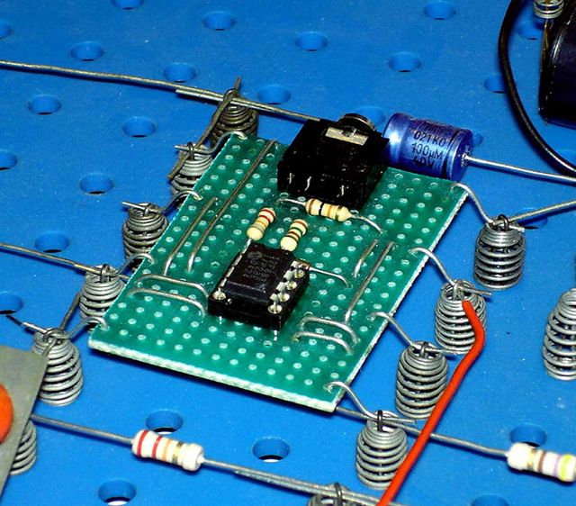
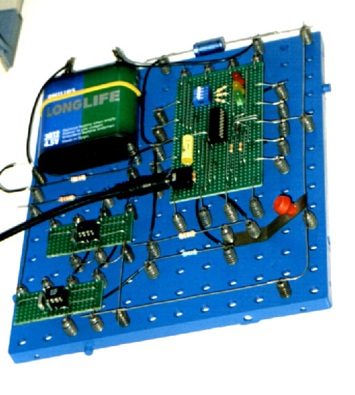
Almost all my PICAXE development and experimenting is done using vero-board modules with I/O and other connections to 0.2" screw terminals. All mounted on cut-to-size ex-pizza base packaging polystyrene held on with masking tape.

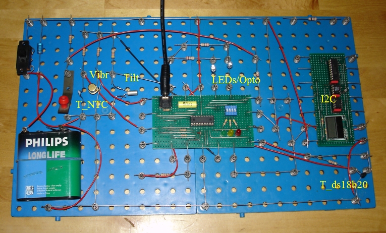
There's a board per PICAXE size plus boards with screw terminals for PSU, I2C Eeprom, serial interfaces, IR Led, IR receiver, DS18B20, LDR, NTC thermistor, 433MHz transmitter, receiver, etc, etc, even 74HCxx inverters - if something's used it becomes a permanent board.

The processor boards are easy to use standalone ( always ready-to-go, just connect power ), quick to connect together and easy to use with breadboard. Boards are not tied down to use with PICAXE. The big advantage is that every board is well documented, connectors are easily identifiable and the circuit never changes from one day to the next. Saves a lot of time knowing the basic circuit is going to work each and every time, leaving only connections to get right.

Board circuits are designed to be easy to use so, for example, I2C boards have the pull-ups fitted on each with links to disconnect those if using multiple boards. Thinking, designing and documenting up front brings dividends later.

Attachment quality low to meet upload restrictions - That's an 18/A/X board which includes a parallel LCD connector plus serial interface with links to add/remove blocking diodes and change 22K etc.
 

Attachments

Last edited:

blauer

Member
hello,

Yes. Two regs. These regs are 7805 for everything and 7806 for servos. I use 12v input so its enough for stepper motors.

This project board is made by me and my college Katila. We fed up using broject board again and again with picaxes. Why can't axes be there always readily and some input and output stuff to assit?
 
Last edited:

BCJKiwi

Senior Member
@Blauer,

So can you produce bare boards (in English) for Picaxters to assemble themselves? I'm sure there would be a demand for them at a fair price.

Have you found the breadboard section itself to be large enough?

As you have 2 voltage regulators and there is only 1 obvious capacitor, what smoothing do you have around each regulator?

Thanks
 

Mycroft2152

Senior Member
Blasuer,

Very nice PICAXE Development board!

I can recognize all the copmponents except the silver cube on the bottom right. What is it?

Any chance for a photo of the bottom of the board?

Myc
 

blauer

Member
>So can you produce bare boards (in English) for Picaxters to assemble >themselves? I'm sure there would be a demand for them at a fair price.

Don't know. Have to think about that...

>Have you found the breadboard section itself to be large enough?

It has been... so far.

>As you have 2 voltage regulators and there is only 1 obvious capacitor, what >smoothing do you have around each regulator?

None. 12V input power is regulated 2A power source. 5V and 6V are smooth when you watch it with scope. With load and without. To the breadboard i add capacitors to be sure. Things have worked so far ;-)
 

demonicpicaxeguy

Senior Member

My babies.:)
awww they're so cute , thats also a very well taken photo i'd swear it's been taken professionally

i've got somthing similar with a 28x that also has a pair of 24lc256 chips as well as the 16mhz resonator
i'd post a photo but it's in my roof space logging tempreture and humidity it's a lot of effort to get up there
 
Ooh. I love showing off pictures.

I used small breadboards from All Electronics to build up the nodes for my version of Jurjen's SerialPower network. Here's a picture of the master node:

http://www.bramblyhill.com/Picaxe/Images/masterNode.jpg

And here's another (much lower quality) one of it sandwiched between two pieces of plexiglass:

http://www.bramblyhill.com/Picaxe/Images/Photo004.jpg

Here's a slave node:

http://www.bramblyhill.com/Picaxe/Images/enviroSensor.jpg

And here's my large breadboard with a terminal set up on it to read data from the SerialPower network:

http://www.bramblyhill.com/Picaxe/Images/displayAndControl.jpg

Funny story about that big breadboard: I bought it in 1988 so I could follow along with the "Basic Electronics Course" published in Popular Electronics that year. The first thing I built was the 5-volt power supply in the upper right corner. It sat in that corner of the breadboard for almost 20 years. Then earlier this year I decided to rebuild the power supply to make it a more compact and I noticiced that for the last 20 years the ripple capacitor was hooked up incorrectly, from the ground pin of the 7805 to the breadboard ground.

I suppose the moral is you should always check your wiring at least once every 20 years. You never know what you might find...

Chuck
 

womai

Senior Member
Ok, here's the complete single channel breadboard version of my low-cost scope - now it includes pre-amplifiers, trigger pickoff & schmitt trigger, adjustable gain amplifiers (for both channels), DACs for level offsets (separate for each of the two channels) and trigger level control.

The only thing missing compared to the future printed circuit board are the two 7805 regulators (one for digital supply, one for analog supply).

Analog bandwidth around 500 kHz.

Enjoy!

Wolfgang
 

Attachments

Last edited:

kranenborg

Senior Member
I always use my now more than 25 years old Philips EE system (a system very well known in Europe for those in their end-thirties - begin sixties now, see http://www.kranenborg.org/ee/ ) for breadboarding. The photos below show examples of how a 08M and 18X (still my favorite picaxes, even with newer ones available) are applied in practice on this system:


See also my picaxe satellite contribution ( http://www.picaxeforum.co.uk/showthread.php?t=9236 ) on how this breadboard is used in practice for development:


A very big advantage of this system over most other systems is the level of component re-use (and hence low costs), since components need not be bent on cut; thus I have a lot of brand-new looking components that are actually thirty years old. There must be tens or hundreds of forum users here that have this system still somewhere (with or without dust coverings ...)

/Jurjen
 

Rickharris

Senior Member
Ah How I wish I had retained my Phillips EE set - How many of us got into electronics!

I see you arestill using the original Phillips battery as well Jurjen! :)
 

D n T

Senior Member
Some of the posts on here are awesome, Blauer, very cool, Australians will want them as well.
I though I might post a couple of mine, but The pictures are too big, will have to just read on.

Keep this thread going

Technical, maybe this could be a new section, it would let you know what types of products the users wanted??
 
Last edited:

westaust55

Moderator
This thread almost needs its own section (akin to code snippets) where all can show of their pride and joy.

While my creation is not so much a bread board as an experimenters box (still only partly assembled attached are my efforts over the past weeks, but I still have a small (and ancient) breadboard module to testing prior to final assembly of sections.

Blank area on the top will ultimately have a few more permanent devices and a terminal strip for temporary connection of other modules.

Have started to mount the Ultrasonic sensor on the rear panel and the battery box will go there as well

Ultimately the AXE-022 proto board, a i2c DS1307 RTC board, an i2c EEPROM board (the AXE-111), a 90mm diam piezo speaker, and other bits will mount inside the box on the bottom half.
 

Attachments

Last edited:

inglewoodpete

Senior Member
Stand-Alone Daughter circuit

Some months ago, I published my stand-alone minimum operating circuit, which behave a little like a flexible daughter board.

The hardware has the benefit of running stand-alone, as well as plugged into a breadboard or can even be plugged into an actual PICAXE socket on a circuit board if required.

The version shown is an older 28X, requiring a resonator. For detail of the original thread, see http://www.picaxeforum.co.uk/showthread.php?t=7711
 

Attachments

Top