BoB Biped

reynoldsw87

New Member
Merry Christmas Ladies and Gents,

I have been looking around the forum and have finally got around to posting on here. I hope I have posted this in the right place (if not admin please can you move it). I have used design circuits and boards around Genie chips but would like to upgrade to Picaxe for more advance projects and take the opportunity to introduce it to the school I have just started working at.

A while back I saw this on instructables and being the holidays I have finally got 5 minutes to build one (http://www.instructables.com/id/BoB-the-BiPed/). I would like to customise it a little by having an LDR so that it can sense darkness, piezo to speak and leds to add light.

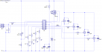
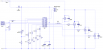
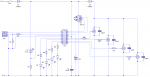
I am fortunate enough to have access to pcb making equipment and would like to design my own board around the 18M2 chip. I have used the manuals on-line to check that I have interfaced the components correctly but would be grateful if someone could cast an eye over it.

Power: 4 x 1.5V AA (non rechargeable)
Inputs: LDR, Ultrasonic Range Finder
Outputs: 4 x micro servos, 4 x 3mm LEDS, 1 Piezo

Many thanks in advance.

Will
BoB_CD1.PNG
 

nick12ab

Senior Member
First of all the pin the LDR is connected to does not have ADC so you will only be able to detect whether or not it is above a certain level, which you can't change in code.

On that programming socket in Circuit Wizard, PR is Serial In and ST is Serial Out. If you allow Circuit Wizard to attempt to autoroute a PCB design or you design it yourself based on the nets it shows, the connections to the socket will be wrong.

What voltage are the miniature servos? You have two diodes between the 6V battery pack which leaves 4.6V left for the servos. Will the servos operate at that voltage?

The circuit has a decoupling capacitor for the PICAXE (which others often don't include), however you should also include a 100µF bulk capacitor.

I hope I have posted this in the right place (if not admin please can you move it).
No you didn't - you posted in the Finished User projects area.
 

reynoldsw87

New Member
Thank you for your quick response.

I have asked the mod/admin to move the thread. (Sorry about that)

Changed LDR to pin 1 so it now has ADC.

Moved the download socket connections. I was going to route it myself, I have seen what I did now, just copied 123 off the manual and not check what they are.

Checked voltage of servo, they will run off 3 volts but have removed the diode and just put it to regulate for the chip.

Have I added the bulk cap in the correct place? I have just gone from what I knew with Genie but wasn't sure if that was correct for Picaxe.

BoB_CD2.PNG
 

nick12ab

Senior Member
Have I added the bulk cap in the correct place?
Yes, however you have now repositioned the diode to an unsuitable place.

So is the distance sensor is designed to run from 6V?

The maximum voltage permitted on a normal I/O pin on a PIC is Vdd+0.3V but the distance sensor (and even the LDR circuit in extreme circumstances) can output more than that because of their higher power supply voltage (0.7V more than the PICAXE).
 

AllyCat

Senior Member
Hi Will,

Welcome to the forum and a Happy Christmas.

... piezo to speak ...
Have you actually tried this? Piezos tend to be very "disappointing" for anything except a simple optimised-frequency (resonant) tone. Also, it would be wise to drive it from a PWM-capable output pin.

IMHO all aspects should be prototyped/breadboarded before starting to make a PCB design, but certainly the acoustic performance of a piezo versus mini-loudspeaker, and the potential need for a sounding board/baffle and/or amplification/coupling capacitor.

Cheers, Alan.
 

reynoldsw87

New Member
I have dropped the piezo from the project. It was just an extra element for students to have when programming.

Don't worry I will breadboard the project before making the PCB. I am writing a blog of how I have made the project for my students to use when attempting their GCSE portfolio so I need to go through the stages that they would.

I have tested the servos today and they work fine at 6Vs, they have an operating range of 3.7 to 7v.

I am going to use a SR00F with a 3pin set up, which I have indicated using a 3 SIL socket.

Can you see any other problems with the circuit?

BoB_CD4.PNG
 

Goeytex

Senior Member
Schematics do not necessarily show the physical locations of components unless noted.

That being said, a bulk capacitor should be physically located on the motor supply rail as close to the motors as possible. This capacitor prevents voltage sags when the motors start. I would suggest from 200uf to 1000uf depending upon the initial current draw of a motor and whether or not all of the motors can possibly start at the same time.

Another bulk/filter cap can be placed near the cathode of the diode. This is for the Picaxe circuitry (LEDs) and the range finder. I would suggest 100uf.

The Picaxe bypass capacitor ( 100nf) should be physically located as close as possible to the Picaxe +V pin.

You show 330 ohm resistors for the LED's. This value provides near maximum brightness at the expense of increased current. If they are RED LEDs consider 2K resistors unless you need to blind the students. For GREEN LED's I would suggest 680R or 1.2K. Battery life will be extended.
 
Top