Bike Alarm ( sorry but help!)

Using PICAXE programming editor to make a bicycle alarm, trying to do this..

Key Switch on
|
green led high
|
siren high 1 sec
|
tilt switch on? --------no?--------(this goes back to "key switch on")
|
yes?
|
red led high 8 secs
siren high 8 secs on low volume
|
key switch off? --------no?--------(this goes back to "key switch on")
|
yes?
|
red led high 30 secs
siren high 30 secs

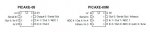
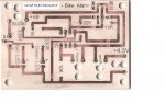
This is it. In the attachment I think pin 1 is labelled wrong, maybe you'll know which one is pin 1 .. And then I don't know what to do once I know which one is Pin 1, like my teacher said. (By the way, my teacher is very unhelpful so I'll need a lot of cooperation, thanks!)
 

Attachments

SilentScreamer

Senior Member
Firstly, will you please actually act on our advice, you're not the only one with a useless teacher, mine can't even design a board for a 08M and decade counter, never mind write code.

Anyway now onto help, pin one is labelled correctly (I think) and the circuit appears to be fine (assuming you have the correct transistor and solder it well-ish). Do you have the programming editor installed at home? If not install it.

Also go to page 24 of the below link. Work out what all your legs do (as in are they in input/output, if so what are they connected to). I'll give you your first one as an example: In3 = Trigger

http://www.picaxeforum.co.uk/docs/datasheets/picaxe_manual1.pdf
 
If pin3 is the trigger then why is it linked to the 22K resistor? or am I wrong..
what I did was turn the PCB over and then go 1, 2 , 3 then traced pin 3 to the 22K resistor..?
 

Andrew Cowan

Senior Member
That's pin 2 attached to the 22K.

Pin 3 is physical leg 4.

Go to manual one and look at the layout for the 08M. Then fill out the table below:

Code:
Physical leg:          Pin number:      Connected device:
     7                      ?                    ?
     6                      ?                    ?
     5                      ?                    ?
     4                      ?                    ?
     3                      ?                    ?
And no, we're not doing it for you - this is your project.

A
 
Last edited:

SilentScreamer

Senior Member
If pin3 is the trigger then why is it linked to the 22K resistor? or am I wrong..
what I did was turn the PCB over and then go 1, 2 , 3 then traced pin 3 to the 22K resistor..?
Notice I put in3 not leg 3. Look at link I supplied on page 24 (or look at the attached screenshot).

Do you now understand what the difference is?

EDIT: Also take note or how legs are labelled in the diagram (as in 1-8) it goes down one side then up the other. Not across the width of the chip.
 

Attachments

Last edited:

BeanieBots

Moderator
I'd say physical leg 1 was labelled correctly and as stated by Andrew, input 3 is physical leg 4.
It's physical pin 2 (serin) which is actually connected to the 22k which is correct.
 

lbenson

Senior Member
Fourth thread with the same question. No evidence that anything suggested before has been tried. You might do best to spend the time to go back and do everything which has been suggested. Then return with questions about the parts which you don't understand. No need to start new threads.

Note that the board you have shown is looking from the underside of the chip--that might explain your confusion about which leg is 1.
 
Last edited:
It is a PICAXE 08 not an 08M..

Physical leg: Pin number: Connected device:
7 1K
6 330
5 330 (and green LED?)
4 10K (AND trigger?)
3 Looks like nothing to me?!

Then? Help!
 

SilentScreamer

Senior Member
It is a PICAXE 08 not an 08M..

Physical leg: Pin number: Connected device:
7 1K
6 330
5 330 (and green LED?)
4 10K (AND trigger?)
3 Looks like nothing to me?!

Then? Help!
The resistors are unimportant (for this question atleast). Look what the 1K resistor is connected to. A transistor, then your siren. So what are the 330 ohm resistors connected to and what is the pin number of the inputs/outputs. (This is found on the attachment I linked, both 08 and 08M are on there, for this there isn't much difference between the two anyway).
 

lbenson

Senior Member
And fill in the other column in Andrew's list--the pin number. The basic program which you write will use pin numbers, not leg numbers.
 
thanks for that...
then it would go
7)Siren
6) Red LED
5) Green LED
4) Trigger Switch (i think)
3) nothing
2) The socket
1) Don't know i'm afraid
 

Andrew Cowan

Senior Member
Just a sidenote - you have connected the buzzer to leg7 (serial out). This means the buzzer will sound as the program downloads. You won't be able to program the PIC unless you work out the pin number for each leg. Look at post 5 - it tells you all you need to know.

A
 
Last edited:
Siren = Output 0
Red LED = Output 1
Green LED = Output 2

The problem is I don't know what corresponds with trigger and the on/off switch but other then that can you get me started on the actual program?
 

Andrew Cowan

Senior Member
The on/off switch is not on an input - it just controls power to the whole chip. You pointed out that the trigger is on leg 4 - what input pin is this? No-one will write the program for you in any way. This is meant to be your GCSE project - if you haven't made and designed the PCB, what have you done?

A
 

SilentScreamer

Senior Member
then that can you get me started on the actual program?
This is something that everyone should do before writing a program. Many people do it mentally (myself included) but they do it never the less. How else could you tell the chip whats on which pin?

Once you have your input pins name sorted (post it and we'll happily check) then write the following lines of code.

For each input (image it is on input one):

Code:
symbol {NAME OF WHAT IS CONNECTED} = pin1
For each output (image it is on output one):

Code:
symbol {NAME OF WHAT IS CONNECTED} = 1
The symbol command renames the name of each pin. I.e. you can use:

Code:
high {THE NAME OF WHATEVER YOU WANT TO USE}
Rather than,

Code:
high 1
It just makes the code easier to understand.
 
Yes the trigger is on leg 4 which is..Input 3!

By the way what does "image it is on output one" mean thats annoying me!

Other than that, is that all I need
the red LED - output1
the green LED - output 2
the siren - output 0
the trigger switch - input 4
?
 
Last edited:
Once the key switch is on
|
output 2 high
|
output 0 high 1 sec
|
input 4 high? --------no?--------(this goes back to "key switch on")
|
yes?
|
output 1 high 8 secs
output 0 high 8 secs, low volume
|
key switch off ? --------no?--------(this goes back to "key switch on")
|
yes?
|
output 1 high 30 secs
output 0 high 30 secs
 
Last edited:

lbenson

Senior Member
"image it is on input one"

He meant "imagine it is on input one"--for his example. In your particular case, your first input is --what?, you haven't told us, though your pseudo-code does. The trigger, your second input, is, as you yourself say in post 17, input 3 (and the last line of post 17 is inconsistent). The clue in this case is that the "key switch," input one, is essentially power-on to the picaxe chip.

You are getting closer. Again if you follow the suggestion and use symbols instead of pin numbers, your code will start to make more sense to you. For example, as suggested above,
Code:
symbol greenLED = 2

main:             ' this is a label which can be used as the start of your program
  high greenLED   '  this turns on pin 2, which lights your green LED if it is properly wired
Then you have to write the rest of your code, turning on the siren, waiting for one second with both devices on (look up the 'pause' command in manual 2), and then turning off the siren. Then you check to see if your trigger is on--make that chart of 1) device; 2) leg; 3) pin to make sure that you know what you are turning on and off and checking for input. (Note that whatever follows the single quote in a picaxe basic line is a "comment"--it is not executed but describes for human readers what the statement is doing.)

Even the three lines in the code box above (of which "high greenLED" is the only executeable one) can be run in the simulator. You should try it NOW so that you can see how the code works. In the window titled "Simulation", next to the image of the chip the "2" button is green (a coincidence in this case--green in the simulator means that the pin is "on" or "high") A little time spent learning the simulator will save you a lot of time later. Then as you add more statements, you can see how they work. You can write all of the code without having any hardware. Of course, the proof is when you actually wire up your design, code the picaxe, run the program, and operate the hardware.
 
Last edited:

Andrew Cowan

Senior Member
To put a pin high for 2 seconds, you neeed to put it on, wait two seconds, and then make it low for two seconds. Can you work out what command to use to wait for two seconds?

A
 

SilentScreamer

Senior Member
Thanks for the better explanation lbenson. Chips, try the example code he supplied, download it to your board if you can (assuming you've soldered it), else the simulator will work well enough. Have you wrote the code that I said in post #16 yet?

When I said "imagine it is on input one" I meant that image that whatever you labelling is on input one (see lbenson's example in post #20).
 
Last edited:
What does the "pause" command do and how is it related to the siren?
Will the keyswitch have a pin number?
What is the IF command and how can I use it in my circuit?
"imagine it is on input one" - but why?
 

SilentScreamer

Senior Member
I said imagine it is on input 1 because in the code I wrote "symbol {NAME OF WHAT IS CONNECTED} = pin1" would have renamed input 1, therefore I said it so you understood my example. Below is lbenson's example.

"symbol greenLED = 2" the renames output 2 to green LED.

Clearer now?
 

SilentScreamer

Senior Member
Pause: Have a guess, wait a bit, pauses your code for X amount of time. For example: "pause 1000" makes the code wait for one second (one thousand milliseconds).

If: Does something if something has happened. For example this will check the trigger to see if it is on, if it is then it will turn the green LED on for one second:
Code:
If trigger=1 Then
high greenLED
pause 1000
low greenLED
EndIf
 
If key switch=1 Then
high redLED
high Siren
pause 3000
low siren

Am not sure whether the keyswitch is an input, If so is it input1, because input 3 is the trigger and there is no input 2..?
 

BeanieBots

Moderator
This is the sort of confusion that comes from copying somebody elses work and not originating the design yourself.

How about demonstrating to everyone that you actually are prepared to put in even the smallest amount of effort.

Draw the circuit diagram and post it.
After you have done that, nearly all your questions will be answered.
 

Andrew Cowan

Senior Member
I've already told you this - the keyswitch is not an input, it turns off and on power to the whole chip.

Read the manuals, and work this stuff out yourself . Your coursework will need a circuit diagram - you need to make one. Don't expect us to do your project for you. It would be worth referencing to this thread in your coursework.

A
 

hippy

Ex-Staff (retired)
@ chipsnfish : You have already deduced the circuit connections from what you have posted in your replies, and you should have a document in front of you which looks similar to the following -

Code:
Leg 1 :               Power in, 4.5V via keyswitch ( on/off )
Leg 2 :               Download Serial In
Leg 3 :               Not connected / Not used
Leg 4 : Input  Pin3   Trigger switch, active high
Leg 5 : Output Pin2   Green LED, active high
Leg 6 : Output Pin1   Red LED, active high
Leg 7 : Output Pin0   Siren, active high ( and Download Serial Out )
Leg 8 :               Power in, 0V
From that you should be able to draw a functional block diagram, then, with a little more effort, a complete circuit diagram.

Once you have done either it should become very clear what inputs and what outputs you have, and in particular how the keyswitch works.
 
Top